Interface Electronics
Guided Laboratory 01 & 02: Webreport, LTSPICE and data Converters
GroupA, ***910 A, ***726 P
|
|
Laboratory Goals
The objectives of this laboratory session are as follows:
- Introduction to LTspice
- Designing a Low pass with 3dB and simulating it.
- Introduction to creation of a web report.
- Preparation for the simulation of a data convertor.
Introduction
- LTspice: is a circuit simulator used to simulate circuits before the real implementation.
- Using a web page to publish a report is possible by editing a raw html code.
It is also possible to insert LTspice schematics to the web page since a code was written by the instructor of this subject which is capable to read a
LTspice schematic file and present the schematic in the web page.
LTspice Low Pass Filter
| The following LTspice schematic of a low pass filter was designed and simulated with a voltage source (sine,AC), R = 100k and C1 = 50 n, with three different simulation commands (.Op, .tran, .AC) : |
|
LTspice Low Pass Filter
| The following figure shows the designed and simulated low pass filter circuit: |
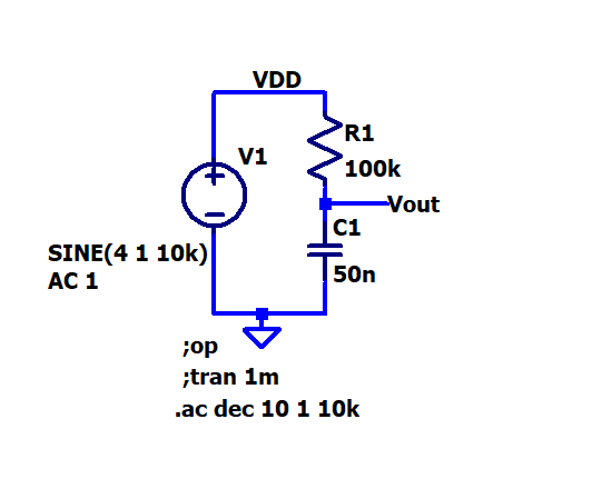 figure 1
|
Low Pass Filter Operating Point
| The following figure shows the operating point of the simulated low pass filter. |
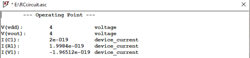 figure 2
|
Low Pass Filter Simulation
| The following figure shows the transient output of the simulated low pass filter. |
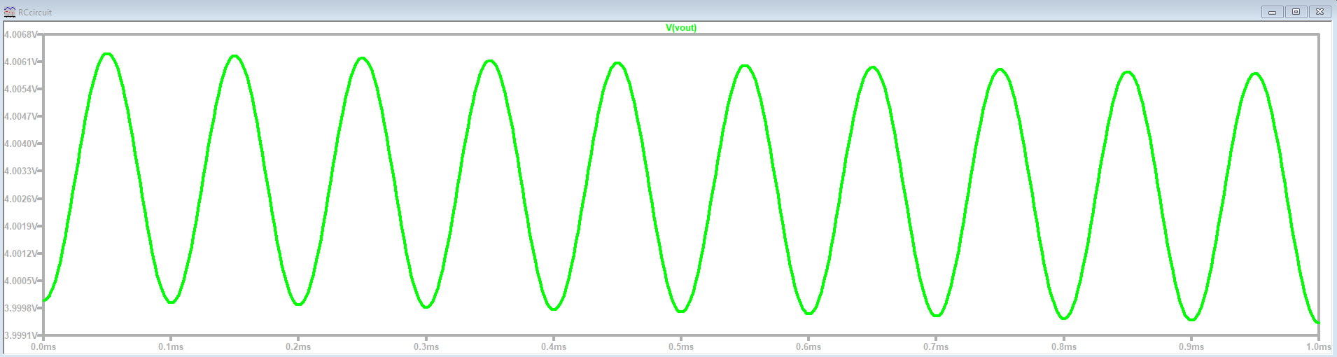 figure 3
|
Low Pass Filter Simulation
| The following figure shows the simulated output of the low pass filter. |
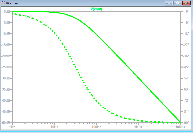 figure 4
|
From the simulation result, it is clear that the low pass filter characterstics matches the simulation output.
Challenges and Difficulties
While implementing this laboratory session, some challenges and difficulties were faced. These challenges and diffeculties are listed below:
- Downloading and unzipping the (web_Template.zip) folder needed some time.
- Getting to know how to edit the raw web page code and being able to pulish a report was a big challenge.
Lessons Learned and Time Spent
The following lessons were learned out of this lab:
- Simulation using LTSPICE.
- The following three commands in LTspice:
- .op Simulation command for operation point.
- .tran simulate over time period T=1/f to see a couple of periods.
- AC simulates a frequency sweep.
- Many commands to edit the structure of the web page were learned include:
- Specifying the sections of the document
- The tab name in the browser.
- Adding comments.
- A section for a new slide.
- A header in a slide section.
- Writing a text inside a slide section.
- Inserting pictures from a folder.
- Inserting a LTspice schematic.
The time spent working on this lab was around 8 hours distributed between the lab sessions and the working on the report.
Conclusion
From this laboratory session, we conclude the following:
- Notepad++ can be used to edit the raw html code for the webpage
- A low pass filter was designed and simulated in LTspice using three different simulation commands.
- There was a need to modify the configurations for the privacy of the web page.
Clarification
The work on this lab session including the simulation implementation and work on the report was done in group.
The student with the identification number ***726 implemented the simulation, while the student with the identification number ***910 created this web report.