16 Bit R2R DAC Characterization
07.12.2022 Joerg Vollrath
+ Share page with QR-code
- Share page with QR-code
Today we want to look at the 16 Bit R2R DAC in EEBench.
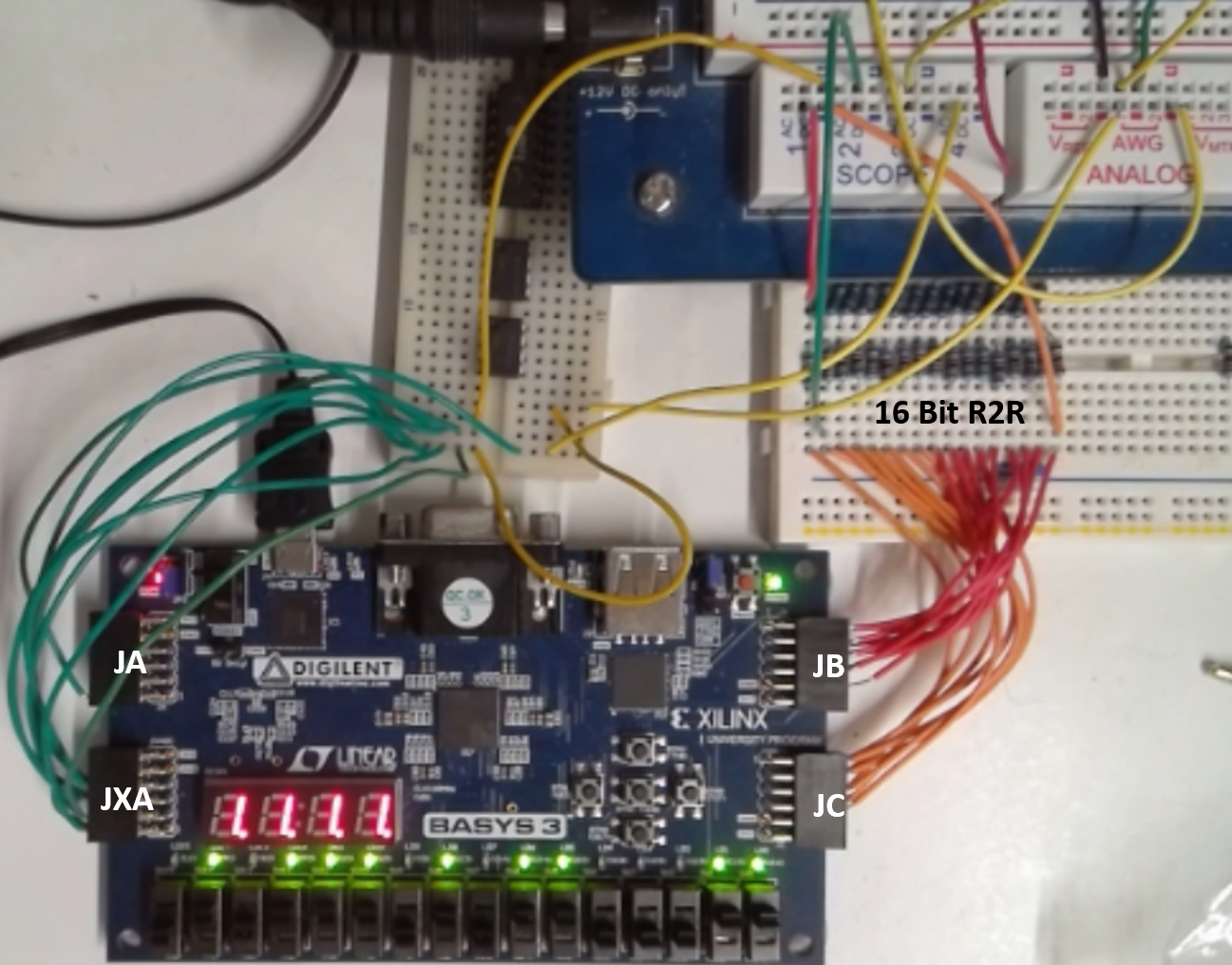
Figure: 16 Bit R2R DAC
The Resistor values are .
Overview
- Connection of R2R to XDAC
- Noise for DC voltage (histogram)
- Settling time
- INL, DNL ramp measurement
- INL, DNL sine measurement
- SNR FFT sine measurement
- Calibration and error correction
R2R connection to XADC
Due to previous experiments Pin 1 has high leakge and can not be used for R2R DAC.
Pin 4 channel 1 can be used. Output of DAC AWG1 has to be limited to 1V.
R = 100.8 kΩ, 2R = 220 kΩ.
Since R is high resistance no voltage divider or opamp is used and the range is limited to
0...3.3V/4 = 0.825 V. offset = amplitude = 0.4125 V. (S000442840FFFFFFF0FFFFFFF)
Sine measurement 1
Measurement C1:
C1 Min: 38.498512 mV
C1 Max: 821.46944 mV
C1 Avg: 414.10679 mV
C1 Amp: 391.48547 mV
C1 T: 499.20000 us
C1 f: 2.0032051 kHz
The minimum is higher than expected. Investigate distortion of other inputs.
Coupling of neighbouring channels
Adjacent channels C2,C3,C4: 500mV offset 400mV amplitude make C1: 38 mV offset and 20mV amplitude.
Noise of measurement channel with DC input
Adjacent channels C2,C3,C4: 0 V DC
C1 Min: 19.760433 mV
C1 Max: 24.917983 mV
C1 Avg: 22.435769 mV
C1 Amp: 2.5787747 mV
C1 T: 31.168955 us
C1 f: 32.083206 kHz
FFT: Total noise -63.26 dB
Sine signal FFT
frequency: 1.4085100 kHz, amplitude: 412.50000 mV, offset: 412.50000 mV
C1 Min: 7.3090715 mV
C1 Max: 784.34424 mV
C1 Avg: 395.83423 mV
C1 Amp: 388.51759 mV
C1 T: 707.20000 us
C1 f: 1.4140271 kHz
| Index | f in Hz | Signal
magnitude
dB | Total
noise
magnitude
dB |
| 3 | 1.4648438 k | -11.39 | -46.22 |
ENOB = (-11.39 - (-46.22))/6 = 34.83/6 = 5.8
DAC error correction
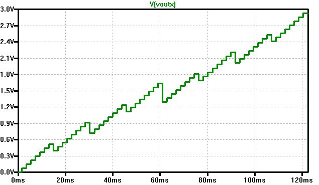
Figure: R2R 3 bit error ramp simulation
LTSPICE: 6Bit_R2R_DAC_Test.asc
Minimum 0V and maximum 2.92 V with slope reversal at 3 MSBs.
Try Excel vlookup(Sverweis) with 32 codes gives
Starting from vlookup manual fit was attempted and could not resolve
INL and DNL for 2 codes (1,30) at the beginning and end.
Reducing the range could make it possible to loose only 1 Bit.
Attention! needed range reduces with reduced number of bits: 63 (6 Bit), 31 * 2 = 62 (5 Bit), 15 * 4 = 60
There seems to be no easy calculation from input code to adjusted DAC code (compare orange and blue line).
INL and DNL stay barely below 0.5 (right axis for grey and yellow curve).
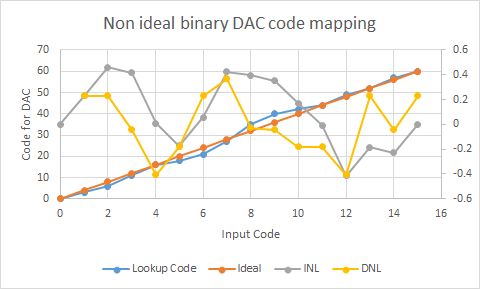
Figure: Mapping 4 Bit input code to 6 Bit output code
| yCode | Lookup Code | Ideal | INL | DNL |
| 0 | 0 | 0 | 0 |
|
| 1 | 3 | 4 | 0.2297571 | 0.2297571 |
| 2 | 6 | 8 | 0.4595142 | 0.2297571 |
| 3 | 11 | 12 | 0.41599184 | -0.04352236 |
| 4 | 16 | 16 | 0.00809729 | -0.40789455 |
| 5 | 18 | 20 | -0.17206464 | -0.18016193 |
| 6 | 21 | 24 | 0.05769246 | 0.2297571 |
| 7 | 27 | 28 | 0.4240888 | 0.36639634 |
| 8 | 35 | 32 | 0.39574927 | -0.02833953 |
| 9 | 40 | 36 | 0.35222657 | -0.0435227 |
| 10 | 42 | 40 | 0.17206464 | -0.18016193 |
| 11 | 44 | 44 | -0.00809729 | -0.18016193 |
| 12 | 49 | 48 | -0.41599217 | -0.40789488 |
| 13 | 52 | 52 | -0.18623441 | 0.22975776 |
| 14 | 57 | 56 | -0.22975644 | -0.04352203 |
| 15 | 60 | 60 | 0 | 0.22975644 |
Interesting is to look at the code difference between lookup code and ideal code.
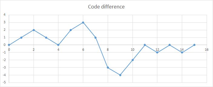
Figure: Code difference of lookup an dideal
Summary