Configuration
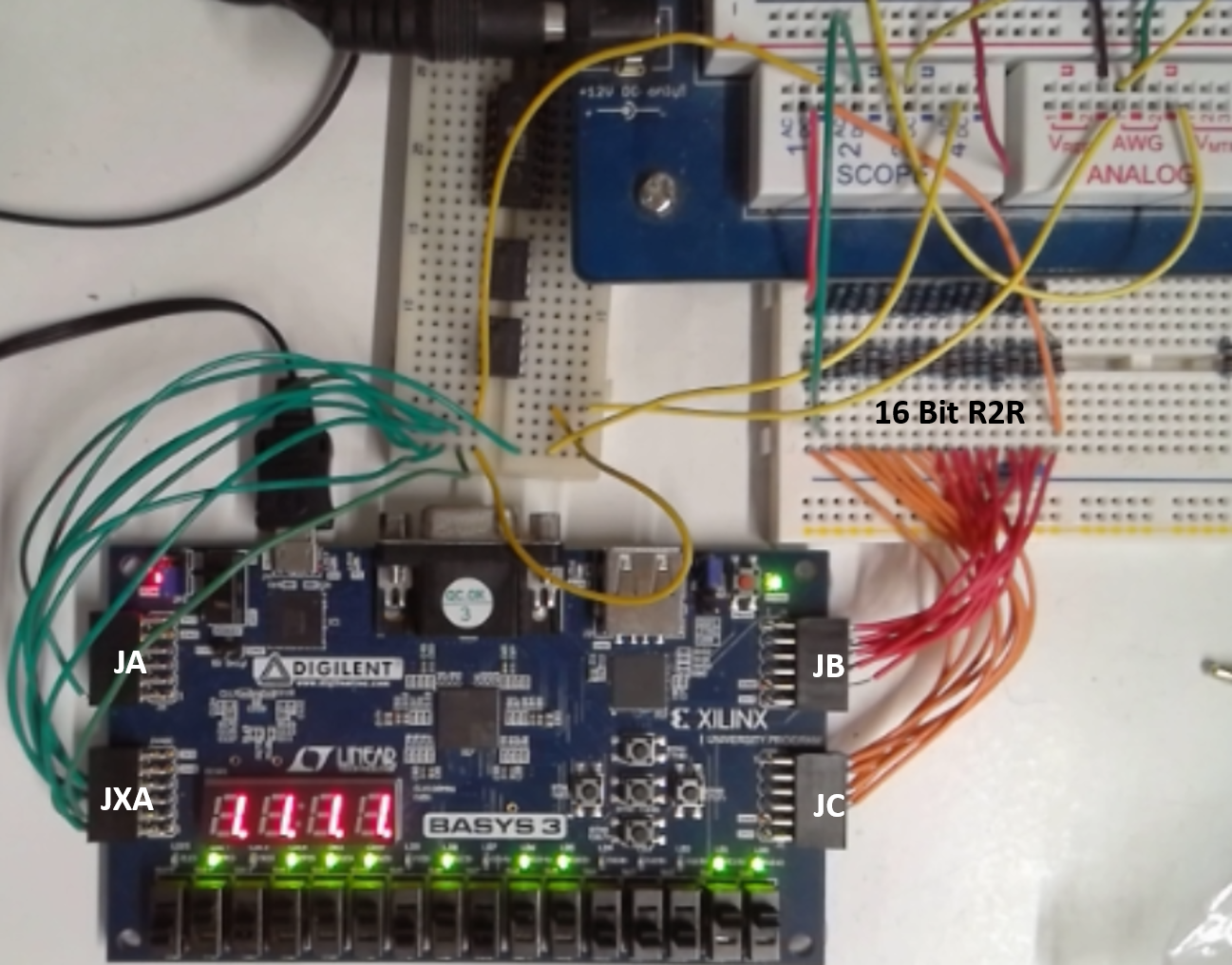
| System: | Board: | BASYS 3 (Raspberry Pi, MKR Wifi 1010) Simulation |
| System: | Communication: | Serial over USB (Serial NodeJs, LAN over USB?, WLAN?) |
| OSC1: | XADC1 (12 Bit, 100 MHz) | OSC2: | XADC2 (12 Bit, 100 MHz) | OSC3: | XADC3 (12 Bit, 100 MHz) | OSC4: | XADC4 (12 Bit, 100 MHz) |
| OSC Sampling time: | 8.32 us | ||||||
| OSC Sampling memory size: | |||||||
| AWG1: | R2R (16 Bit) | AWG2: | None | ||||
| AWG1: | Minimum voltage: | Maximum voltage: | Resolution: | Bits | |||
| |||||||
Sent:
"X": initialize"S": sine signal, followed by 24-hex numbers: step, amplitude, offset each 32 bit
Example f = 1 kHz, amp = 1 V, offset = 1 V as shown in AWG1: S0000A7C526C9B26C26C9B26C
"T": triangle signal, followed by 20-hex numbers: start, stop, step (16-bit each), repeat (32 bit)
Example pulse f = 1 kHz, amp = 1 V, offset = 1 V as shown in AWG1: T00004D924D920000C350
Example triangle f = 1 kHz, amp = 1 V, offset = 1 V as shown in AWG1: T00004D8A001900000040
Example stair f = 1 kHz, amp = 1 V, offset = 1 V as shown in AWG1: T00004D8F0F8300002710
"U": start sending data: 514 chunks of block of data are sent: AWG, OSC1, OSC2, OSC3, OSC4; 16 bit each; 20 hex values
The first transmission has the current index stored. One extra transmission, because there can be an ongoing conversion at the current index.
"V": Connect switches to output