Scientific Project 2020A Web-Interface for a SenseHAT for Raspberry PiSupervisor : Prof. Dr.-Ing. Jörg Vollrath |
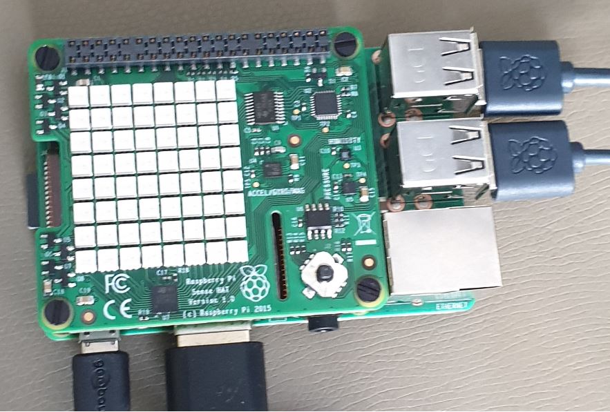
Fig: A Raspberry Pi and a SenseHAT |
1. Introduction
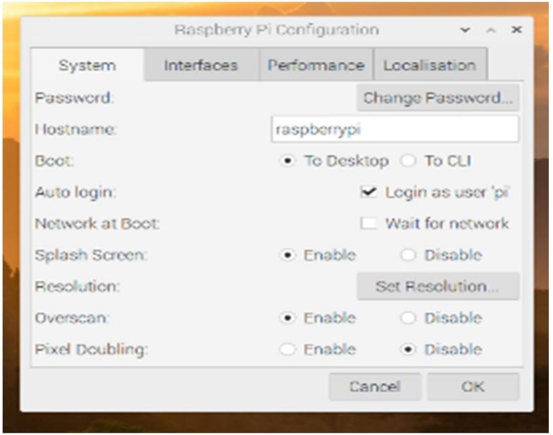
The Raspberry Pi is a great invention of modern science. It is a small single-board computer and can perform many functions similar to a modern computer. If anyone wants to browse the web, write programs and create own circuitry and physical devices, then a Raspberry Pi will help him in every possible way. On the other hand, Sense HAT (Hardware Attached on Top) is a special type of add-on board. It was designed especially for the Astro-Pi space mission. This board allows us to measure temperature, humidity, pressure, orientation and show the output information using its built-in LED matrix [1]. The main goal of this scientific project is to run a Node.js server on Raspberry Pi and to control the LED matrix of the Sense HAT by a webpage. And at the same time, calibrate the color of LEDs of the Sense HAT.
2. Hardware requirements for this project
3. All About Raspberry Pi
|
Raspberry Pi is developed by the Raspberry Pi foundation. This foundation has released several models of Raspberry Pi. In this project, the Raspberry Pi 3 Model B+ is used. This is a low-cost credit card size small computer [1]. The Raspberry Pi 3 Model B+ is the latest product in the Raspberry Pi 3 range, boasting a 64-bit quad-core processor running at 1.4GHz, dual-band 2.4GHz and 5GHz wireless LAN, Bluetooth 4.2/BLE, faster Ethernet, and Power-over-Ethernet( PoE) capability via a separate PoE HAT. The dual-band wireless LAN comes with modular compliance certification, allowing the board to be designed into end products with significantly reduced wireless LAN compliance testing, improving both cost and time to market [2]. |
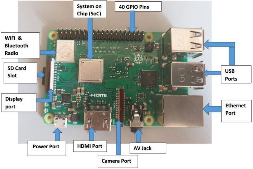 Fig 3.1: Raspberry Pi |
|
• GPIO (General Purpose Input/Output) Pins: Raspberry Pi has 40 GPIO pins. With these pins, Pi can communicate with other devices and electronics. Raspberry Pi can turn these pins on or off. These input pins are used to receive signals from sensors or other devices. On the other hand, the Raspberry Pi uses output pins to transmit data to other devices [1]. |
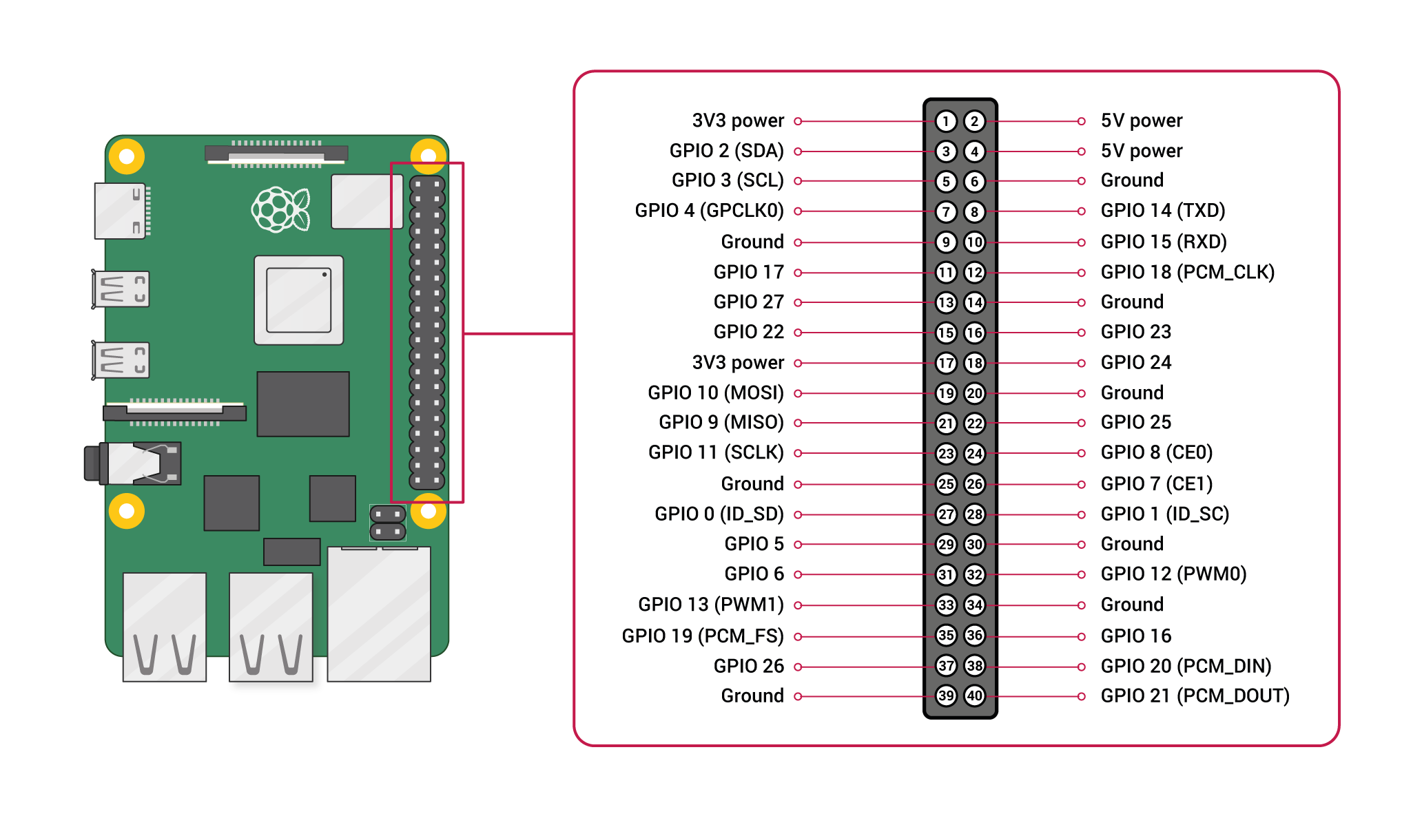
Fig 3.2: GPIO Pins [4]. |

4. Node.js
Node.js is an open-source JavaScript run time environment [8]. Nowadays, it has become more popular in the programming world. It is free and it executes JavaScript on the server-side. Besides, Node.js can work on different platforms (Linux, Windows, etc.) [9].
4.1 Importance of Node.js
Node.js runs in a single process without generating new threads for each request [8]. It can send the task to the computer file system and at the same time, it is ready to manage the new request. When the file system has opened and read the file, the server transfers the contents to the client. Thus, it makes Node.js time efficient. Besides, Node.js uses non-blocking, asynchronous programming. Moreover, Node.js can perform various types of work. For example, it can create, open, read, write, delete and close files on the server. Furthermore, it can create dynamic page content [9].
4.3 Node.js Module
Node.js Module can be considered the same as the JavaScript library. It is a set of functions that can be included in the Node.js file. There are several built-in modules that do not require further installation. The following modules are used to control the Sense HAT display from my website [10].
• Node.js HTTP Module
• Node.js File System Module
• Node.js Path Module
• Socket.io Module
4.3.1 Node.js HTTP Module
HTTP stands for “Hyper Text Transfer Protocol’’. To add this module, we should use the require() method [11].
var http = require('http');
HTTP Requests and Responses are used to create communication between clients and servers. A client (a browser) sends an HTTP request to the web and a web server receives that request. After processing the request, the server returns an HTTP response to the web. Finally, the client receives that response. There are many types of browser requests. Among them, the most common are requests for HTML page, style sheet, JPG image, JavaScript code, and data. In return, a server provides HTML files, CSS files, JPG files, JS files and data (XML or JSON) respectively [11].
4.3.2 Node.js File System Module
The Node.js File System Module allows us to work with the file system on computer and require() method is used to include the File System Module [12].
var fs = require('fs');
The most common uses of the File System Module are read files, create files, update files and delete files [12].
4.3.3 Node.js Path Module
Node.js Path Module is a built-in module. This provides a way of working with different directories and path files. The syntax for including this module is given below [13].
var path = require('path');
4.4. Web-Socket
Web-Socket enables bidirectional communication in real-time over the web. It can be run together with an HTTP server. It creates communication between a server and a web browser [14]. For example, if we select a button of the LED matrix on the webpage and click on the ‘OK’ button, then the respective LED in the Sense HAT will be turned on.
4.4.1 Installation of socket.io
Socket.io creates a two-way channel between a server and a web browser. To install socket.io, the following procedure should be followed [14].
I. Update the system package list
• pi@raspberrypi:~ $ sudo apt-get update
II. Upgrade the system’s installed package to their latest version.
• pi@raspberrypi:~ $ sudo apt-get upgrade
III. Install the socket.io on Raspberry Pi.
• pi@raspberrypi:~ $ sudo npm install socket.io -save
IV. Reboot the Pi.
• pi@raspberrypi:~ $ sudo reboot
To include socket.io module in the server-side, we should use the following syntax [14].
var io = require('socket.io');
On the other hand, the HTML page should also use the below code to include socket.io module [14].
![]()
5. Sense HAT
The Sense HAT is an add-on board for Raspberry Pi. It was made especially for the Astro PI mission- launched to the International Space Station in December 2015 [15]. Sense HAT has an 8×8 matrix that consists of a total of 64 LEDs. These RGB (Red, Green, and Blue) LEDs are programmable. This LED matrix can be controlled to produce any color. Along with this LED matrix, the Sense HAT has a five-way joystick and six onboard sensors [1].
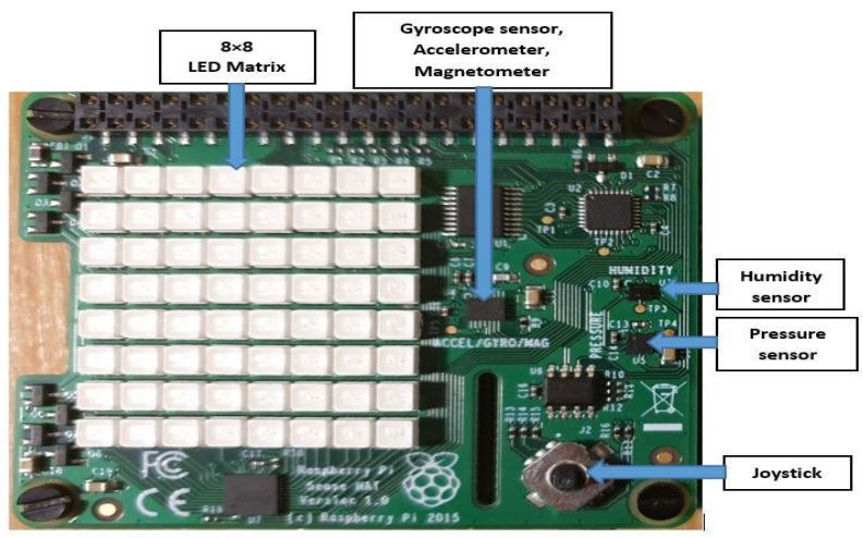
Fig 5.1: Sense HAT.
Gyroscope sensor: This sensor is used to sense changes in angle over time by keeping track of the direction of Earth’s gravity field. This sensor senses if someone rotates the Sense HAT relative to the surface of the Earth [1].
Accelerometer: This sensor is used to measure acceleration forces in multiple directions. Thus, taking data from the gyroscope sensor and accelerometer, we can track where the Sense HAT is pointing and how it is moved [1].
Magnetometer:It can measure the strength of a magnetic field and track the movement of the Sense HAT. It can be used to detect metallic objects and the electrical field [1].
Humidity sensor: This sensor measures the relative humidity of the air [1].
Barometric pressure sensor: It measures air pressure [1].
Temperature sensor: This sensor measures the surrounding temperature. But Sense HAT does not have a separate temperature sensor. It uses temperature sensors built into the humidity and barometric pressure sensors [1].
5.1 Hardware setup of the Sense HAT on Raspberry Pi
When unpacking a Sense HAT, one can find a Sense HAT itself, four metal or plastic pillars known as spacers, eight screws and a black plastic strip. Like the GPIO pins on the Raspberry Pi, this plastic strip has some metal pins. Firstly, push this strip pin-side-up through the bottom of the Sense HAT until hearing a click. Then push the Sense HAT down onto the Raspberry Pi’s GPIO header, making sure to line it up properly with the pins underneath and to keep it as flat as possible. Finally, use eight screws and four spacers properly to protect the Sense HAT from bending and flexing [1].
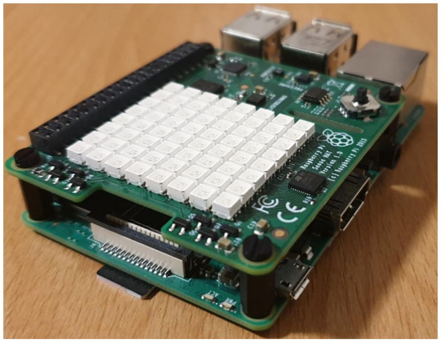
Fig 5.2: Hardware setup of the Sense HAT on Raspberry Pi.
Besides, Hardware Attached on Top (HAT) modules should only ever be plugged into and removed from the GPIO header while the Raspberry Pi is switched off and disconnected from its power supply [1].
5.2 Installation of the Sense HAT Software
To install Sense HAT, we can do the following tasks.
I. Update the system package list
• pi@raspberrypi:~ $ sudo apt-get update
II. Upgrade the system’s installed package to their latest version.
• pi@raspberrypi:~ $ sudo apt-get upgrade
III. Install the Sense HAT software on Raspberry Pi.
• pi@raspberrypi:~ $ sudo apt-get install sense-hat
IV. Reboot the Pi.
• pi@raspberrypi:~ $ sudo reboot
After rebooting the Pi, The sense HAT is installed.
If the LEDs on the Sense HAT are illuminated in a rainbow pattern and then the LEDs are turned off again, this means that the Sense HAT is properly installed [1].
6. Web Interface between Raspberry Pi and Sense HAT
A web interface is a way to control any device by a website. Here, a webserver is created. And when it is running, a user can access the website using URL http://[IP of raspberry pi]:8080. For example the URL is http://10.2.106.135:8080 for the remote users. But for a local user, the URL is http://127.0.0.1:8080. In this website, there are two options. One is “Web Report” for showing my web report and the other is “Sense HAT Display Control” for controlling the Sense HAT display. In the “Sense HAT Display Control” page, color can be chosen from the color picker. Besides, we can select LEDs from the LED matrix on the webpage. There are three options.
• 1st option- it is an “OK” button. If anyone clicks this button, the respective RGB array code will be sent to the server. And after processing, the selected LEDs on the Sense HAT will be turned on. So, the selected LEDs will get the selected color from the color picker.
• 2nd option- it is a “Reset” button. After clicking this button, all LEDs on the Sense HAT will be turned off.
• 3rd option- it is a “Select All” button. After clicking this button, all LEDs on the Sense HAT will be turned on and the LEDs will get the color that is already selected from the color picker.
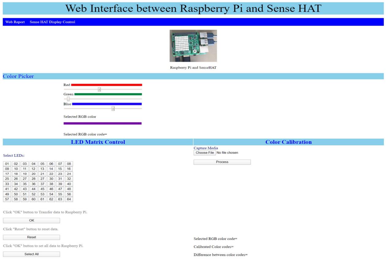
Fig 6.1: Website for Web interface between Sense HAT and Raspberry Pi.
Moreover, there is a “Color Calibration” section. In this section, one can upload an image from the client-side and compare the color code of the uploaded image with the selected color code from the color picker.
7. Description of the program
I have created a folder (named as public). In this directory, I have kept the server code, HTML page, pdf file of the report, and images.
7.1 Webpage Description
This webpage has two parts. One is HTML code and the other is JavaScript code.
7.1.1 HTML Code
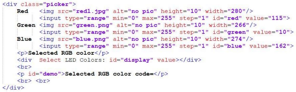
This code (below) is used to create the color picker. Here, we can choose different values (ranges from 0 to 255) of red, green, and blue. As a result, we get a variety of colors depending on the quality of red, green, and blue. The resulted color will be shown in the section (id= ‘display’).
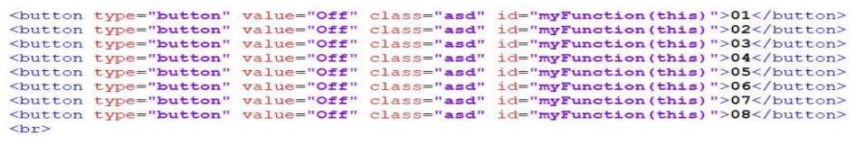
The code (below) is used to create 64 buttons (here only 8 buttons are shown) for the 8×8 LED matrix.
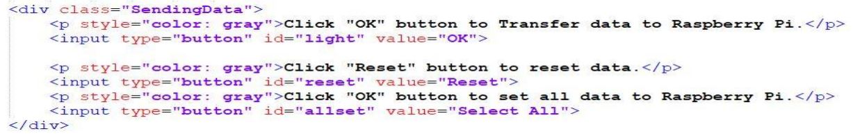
This section (below) is used to create buttons for the "Selected LEDs (id= “light”)", "Reset All LEDs (id=“reset” )" and "Select All LEDs (id=“allset”)" options. By clicking these buttons, button related data will be transferred to the Raspberry Pi.
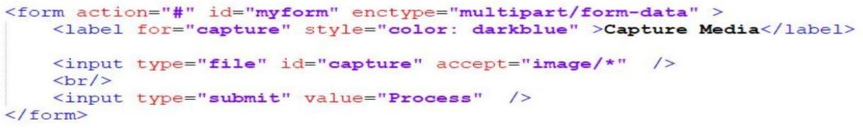
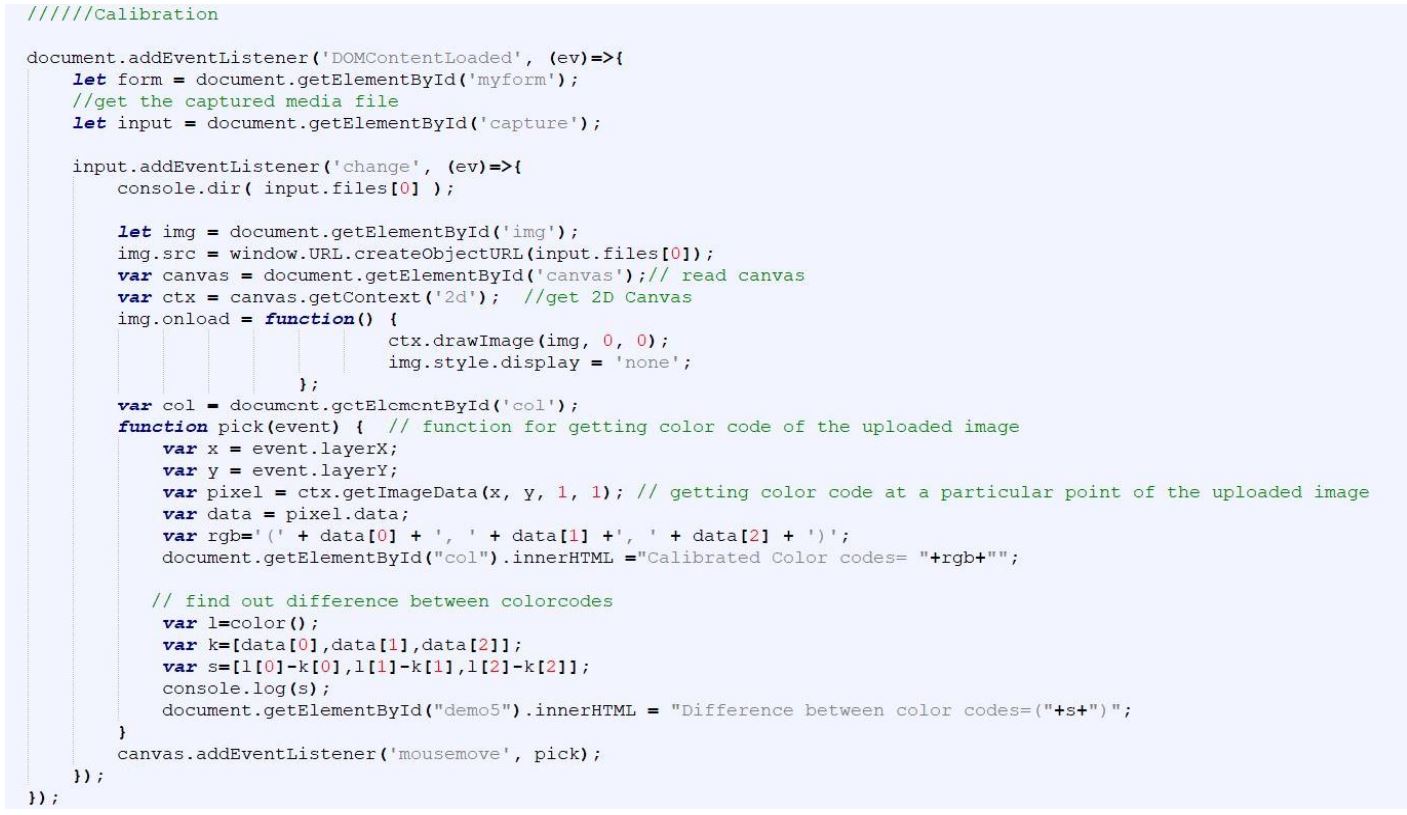
By this part, we can upload image from the client-side.
By using the below code, we can create a canvas where the uploaded image can be shown.
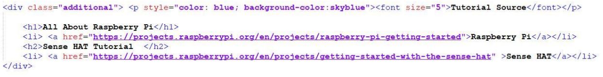
This section (below) is used to get the website links of the Raspberry Pi and the Sense HAT tutorial.
7.1.2 JavaScript Code
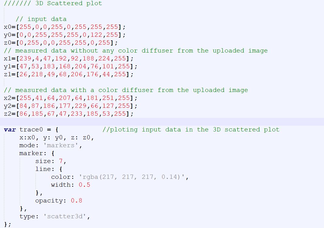
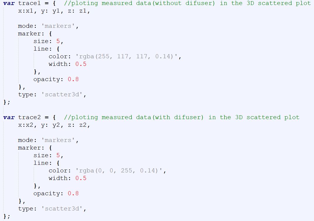
Here, socket.io is a library that enables real-time, bidirectional and event-based communication between the browser and the server [14]. On the other hand, plotly.js is a high level, declarative charting library. Here, it is used to create a 3D scatter diagram [16].

Define socket.io so that it can load socket.io library and the client can connect to the host that serves the page.
This part (below) is used to get input value (string array) of the color picker and convert the string array into an RGB array.
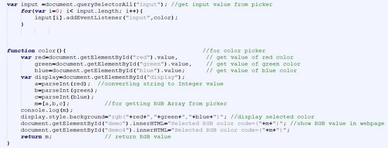
This section (below) is used to color any button on the 8×8 LED matrix on the webpage. This means, we can select or deselect any button simply by clicking that button. And if the button is selected, it will get the color already selected from the color picker.
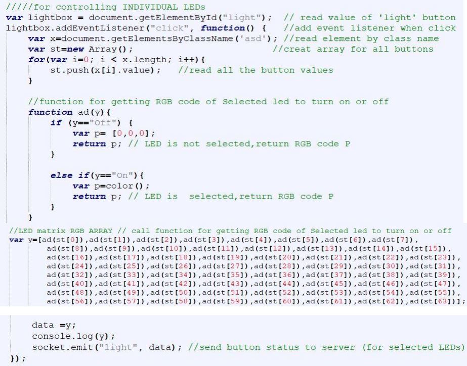
This part (shown below) is used to get data (RGB array data) of the selected LEDs of the LED matrix on the webpage and transfer that data to the server. By clicking this button (button name= “OK” id=“light” ), we can turn on the selected LEDs of the Sense HAT.
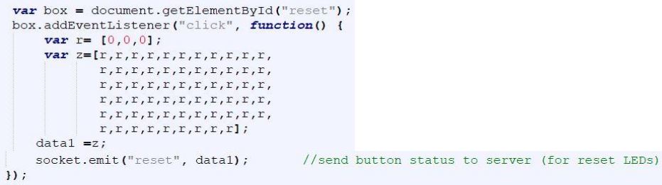
This code (below) deselects all LEDs of the 8×8 LED matrix and sends reset button status to the server. If someone clicks this button (button name=“Reset” id= “reset”), all LEDs in the Sense HAT will be off.
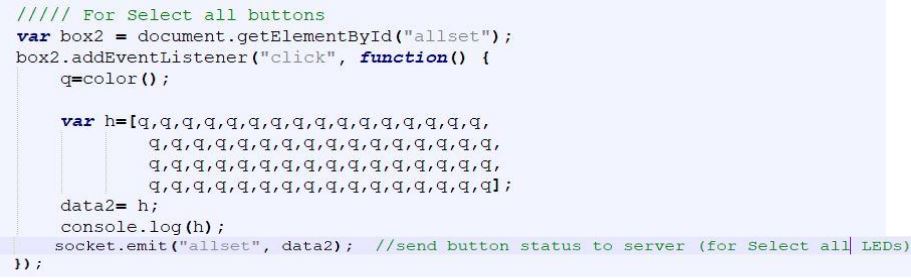
This code (below) selects all LEDs of the 8×8 LED matrix and sends a button (id= “allset”) status to the server. If someone clicks this button (button name= “Select ALL” id= “allset”), all LEDs in the Sense HAT will be illuminated.
In this bottom part, the webpage can upload an image from the client-side and get the color code of any point of that uploaded image by moving the mouse over that image on the canvas. It also shows the difference between the input color code (from the color picker) and the obtained color code of the uploaded image.
In the bottom section, the code is used to plot a 3D scatter diagram.
7.2 Server code Description
TIn this part (below) is used to create an HTTP server. We can open the webpage in a browser using http://127.0.0.1:8080 for local user and http://[IP of raspberry pi]:8080 for a remote user.
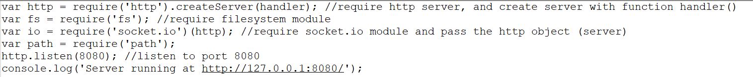
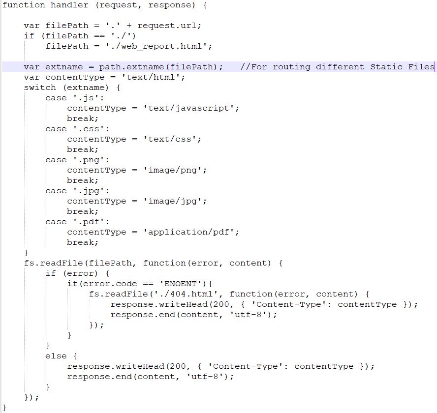
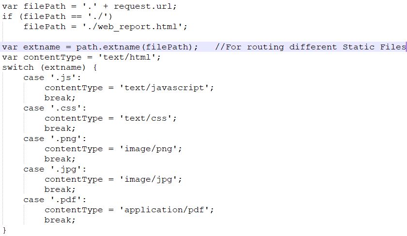
In the bottom section, the code is used to route different static files (for example image files, JavaScript files, and html files.).
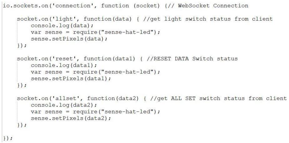
This bottom section is used to set up a communication between the server and the client.
8. Color Calibration
Color Calibration is a kind of comparison between an input color and a measured output color. Here, the color (from the color picker on the webpage) is taken as an input color and the color (from the uploaded image from the client-side) is taken as a measured color. I changed the color code on the webpage (as input to the Sense HAT) and I took some images of the Sense HAT display. I observed that due to the continuously blinking of the LEDs, the exact color of the LEDs could not be shown in the captured images.
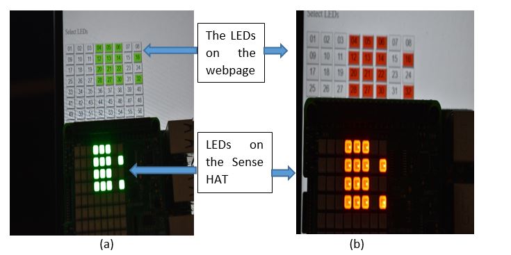
Fig 8.1: Images (a and b) without a color diffuser (paper) over the Sense HAT Display.
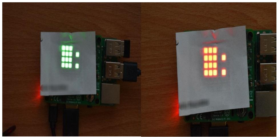
Fig 8.2: Image with a color diffuser (paper) over the Sense HAT Display
Then I used a color diffuser over the Sense HAT display to get almost the same color as the input. It shows that if we use a good color diffuser, we will get an image like the input image. Another problem is, if the display of the Sense HAT is seen with empty eyes, we can observe, the entire LED has almost the same distribution of color. However, when we take a snapshot of the display, the image shows that the desired color becomes thicker at the edges of the LEDs, and we see almost different colors in the middle region of the LEDs. This may be due to the focus and resolution of the camera. That's why the color code changes from one point to another in that uploaded image.
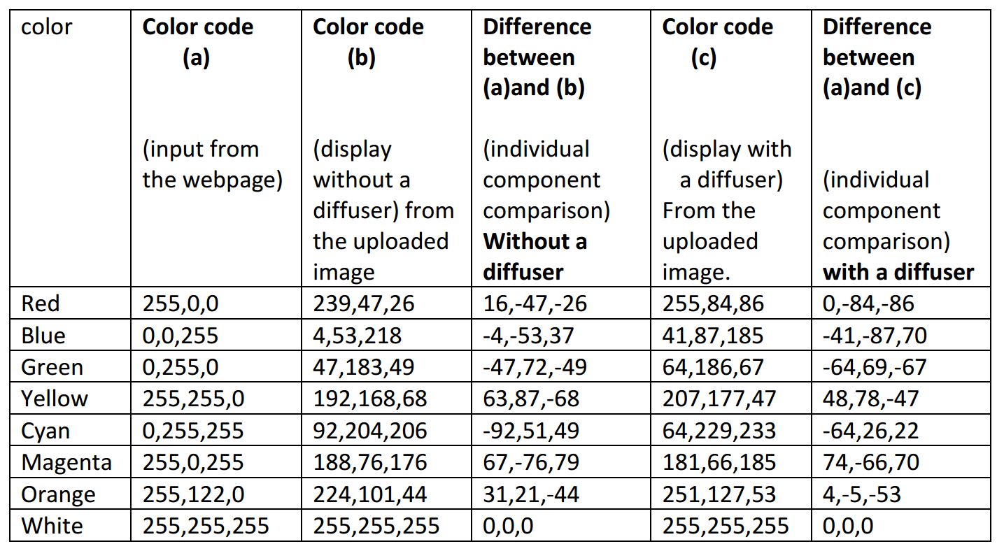
Table01: Input color code (RGB values) from the webpage and measured color code (RGB values) from the uploaded image.
|
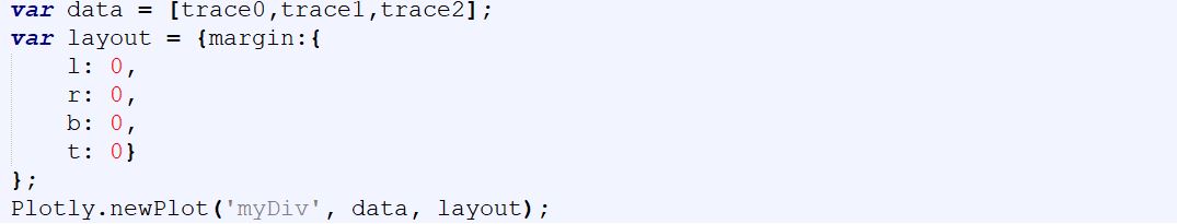
I used plotly.js for adding a 3D scatter plot on the webpage. In the plot, it shows the RGB values of each input color code and the measured color code from the respective uploaded image.Here, the x-axis, y-axis, and z-axis represent the red, green, and blue elements of the color respectively. |
Fig 8.3: 3D scatter plot (Here, trace0 is for input data from the webpage, trace1 is for measured data from the uploaded images (without a color diffuser), trace2 is for measured data from the uploaded images (with a color diffuser). |
9. Challenges
I have faced several problems during this project. Most of them are solved. These problems and solutions are discussed in the below section.
1.One should be careful about the installation of Node.js. I tried to install an older version and wrote command as below,
• pi@raspberrypi:~ $ curl –sl https://deb.nodesource.com/setup_8.x | sudo bash-
But Node.js was not installed at that time.
Solution: I used the latest version of Node.js and wrote command (shown below)
• pi@raspberrypi:~ $ curl –sl https://deb.nodesource.com/setup_10.x | sudo bash-
Then, Node.js was installed properly.
2. Plug the power into Raspberry Pi, and if the LEDs on the Sense HAT are illuminated in a rainbow pattern and then the LEDs are turned off again, this means that the Sense HAT is properly installed [1].
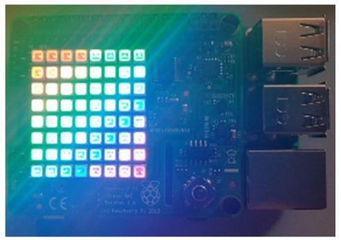
Fig 9.1: Sense HAT display shows Rainbow Pattern.
In my case, after connecting the Raspberry Pi to the power supply, the LEDs on the Sense HAT were always illuminated in a rainbow pattern and never turned off. At that time, I tried to run a Node.js program on the Raspberry Pi to control the LEDs of the Sense HAT. But an error message was shown which is given below,
Error message “OSError(‘Cannot detect %s device’ % self.SENSE HAT FB NAME)” or
Error message “OSError: Cannot detectRPi-Sense FB device”.
Solution: To solve this problem, I did the following tasks-
a) Enabled i2c.
b) Command “RTIMULibDrive11” is used to check which sensors of the Sense HAT is working. But in my case, all sensors except the LED matrix and joysticks worked properly.
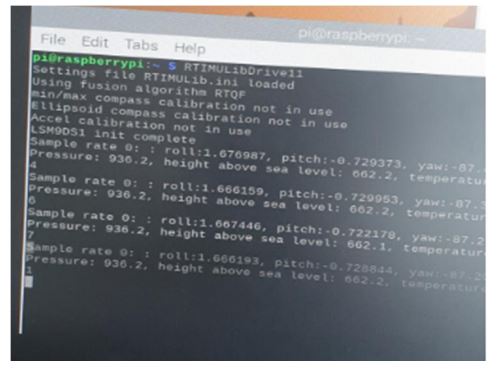
Fig 9.2: Check the sensors of the Sense HAT working or not.
c) Command "sudo i2cdetect –y 1" is used to check whether the GPIO pin works or not. Here, I observed the same thing.
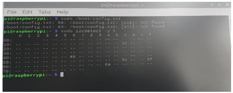
Fig 9.3: Check the GPIO pins of the Raspberry Pi working or not.
d) Then I checked /boot/config.txt file and saw the last few lines were like as the below-
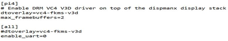 e) After that, I modified this /boot/config.txt file like as below
 f) After rebooting the Raspberry Pi, I observed that the LEDs on the Sense HAT were illuminated in a rainbow pattern, then turned off again. Finally, the Sense HAT worked properly.
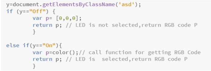
3. I tried to transfer data from the client-side to the server. But the problem was that it transferred a string array instead of an RGB array. For example, when I sent this below button status to the server, a string array [“Off”] was transferred.
![]() But the server needs an RGB array to turn on the LEDs on the Sense HAT. So, the LEDs on the Sense HAT remained switched off.
But the server needs an RGB array to turn on the LEDs on the Sense HAT. So, the LEDs on the Sense HAT remained switched off.
Solution: I used a statement (If-Else) to convert the string array into an RGB Array. An example code is given below.
4. The “onclick” event does not work directly in the Chromium browser.
Solution: I used “addEventListener()” method. But we cannot get return value from “addEventListener()” method. So, we can pass other function to addEventListener() [17].
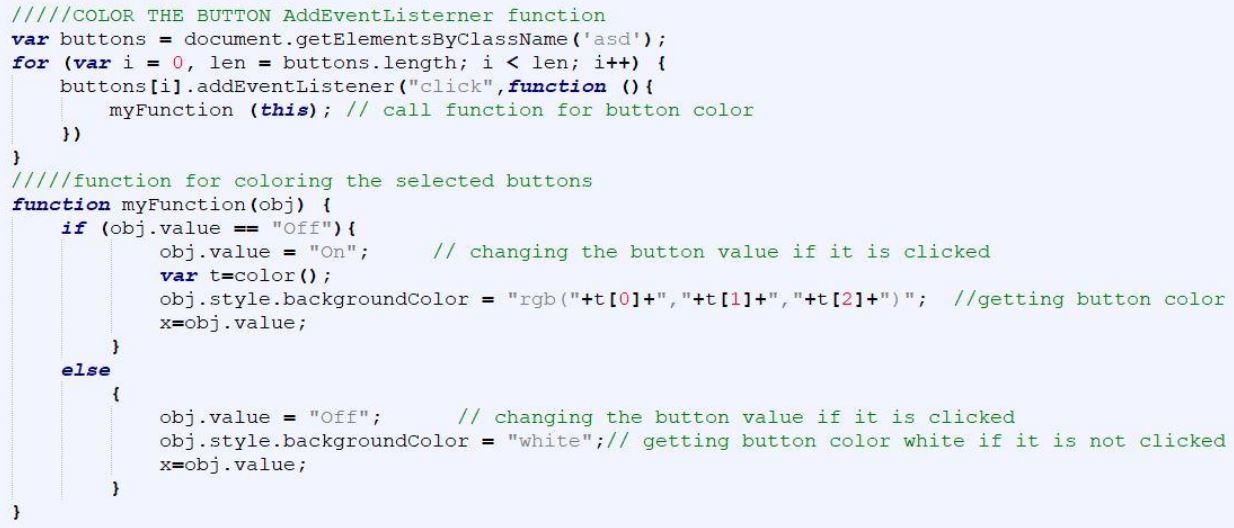
5. I have 64 buttons (for example, one button is shown below) on the webpage for representing the LED Matrix of the Sense HAT. And I needed to get “onclick” button color.
![]() It means, I wanted to get the button color just like the color I chose from the color picker
using the ("this") argument. But, the command line (“buttons[i].addEventListener("click", myFunction (this);”) did not work. That means, the buttons did not get the color.
It means, I wanted to get the button color just like the color I chose from the color picker
using the ("this") argument. But, the command line (“buttons[i].addEventListener("click", myFunction (this);”) did not work. That means, the buttons did not get the color.
Solution: In this case, the command lines (shown below) work and the buttons get color simply by clicking that.
6. For color calibration, we need an image. So, I thought that I would use the browser camera and capture images directly from the browser side. But, I got a problem regarding accessing the browser camera. I installed “getUserMedia” npm in my Pi. But when I run the server, it showed an error "can't read property getUserMedia of undefined". Besides, sometimes it showed an error that, “getusermedia is not a function”. And sometimes it showed “navigator.getUserMedia is undefined”.
Solution: I took some images using a camera and then uploaded those images from the client-side. After that, I can calibrate those images.
7. I wanted to show some static images inside the webpage (HTML). That’s why I kept all static images, HTML webpage in the same directory. But while running the Node.js server, the webpage did not show those static images. Then, I added path directory, but it did not show any image.
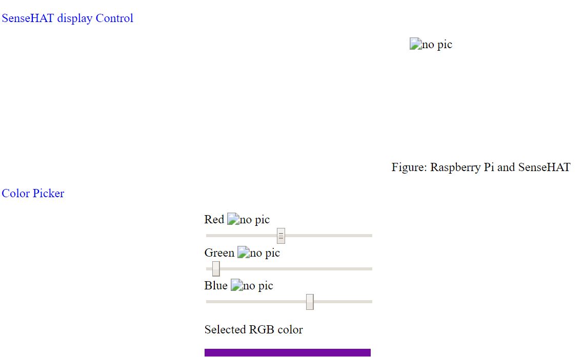
Fig 9.4: The webpage does not show any static image.
Solution: To solve this issue, I used the code (below) to route the image and other static files.
And finally, I was able to display the static images inside the HTML.
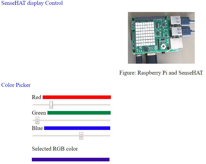
Fig9.5: The webpage shows static images.
Besides, I have found that www.github.com, www.w3schools.com, www.developer.mozilla.org, and www.stackoverflow.com are very informative and these sites offer possible solutions to many questions.
10. Conclusion
During this project, I have learned many things about JavaScript and HTML language. These languages are user friendly. By using these languages, I have created a local server and a website. Besides, Node.js is very important in a server environment. I have gathered a good knowledge about Raspberry Pi and Sense HAT. In this project, I have created a web page that can control the Sense HAT display. So, a user can control the Sense HAT display from a remote place. Furthermore, he can upload an image from the client-side and compare the input color (from the color picker) with the color taken from the client's uploaded image.
11. Future work
In this project, the Sense HAT display is controlled by a webpage. Future work is to create a webpage that can control other sensors in the Sense HAT and after that, we will get a website that can control the Sense HAT completely.
12. Reference
1. Gareth Halfacree “The official of Raspberry Pi Beginner’s guide” Raspberry Pi Trading Ltd, Station Road, Cambridge, CB1 2JH, 1st Edition 2018
2. https://static.raspberrypi.org/files/product-briefs/200206+Raspberry+Pi+3+Model+B+plus+Product+Brief+PRINT&DIGITAL.pdf
3. https://www.raspberrypi.org/products/raspberry-pi-3-model-b-plus/
4. https://www.raspberrypi.org/documentation/usage/gpio/
5. https://www.raspberrypi.org/downloads/raspbian/
6. https://etcher.io
7. https://www.w3schools.com/nodejs/nodejs_raspberrypi.asp
8. https://nodejs.dev/
9. https://www.w3schools.com/nodejs/nodejs_intro.asp
10. https://www.w3schools.com/nodejs/nodejs_modules.asp
11. https://www.w3schools.com/whatis/whatis_http.asp
12. https://www.w3schools.com/nodejs/nodejs_filesystem.asp
13. https://www.w3schools.com/nodejs/ref_path.asp
14. https://www.w3schools.com/nodejs/nodejs_raspberrypi_webserver_websocket.asp
15. https://www.raspberrypi.org/products/sense-hat/
16. https://plot.ly/javascript/
17. https://www.w3schools.com/js/js_htmldom_eventlistener.asp