Microelectronics Laboratory2013 Synthesis of a UARTProf. Dr. Jörg Vollrath |
Outline
- VHDL description of a UART
- Synthesis of a UART with Xilinx Webpack
- Layout library and extension
- Generating structural VHDL with AnalyzeJS.html
- Synthesis of a UART with Electric VLSI Design System
- Summary
This laboratory shows an example of a layout synthesis without using commercial tools.
Timeline
- UART basic run
- Generated VHDL Synthesis File with ISE Webpack: 1 h
- Transfer VHDL code with AnalyzeJS: 1 h
- Start Electric and load library sclib and create uartx: 1 h
- Total: 3 h
- Verification
- Verify Electric primitive cells versus VHDL code: 8h
- Verification of UART in ISE Webpack: 1h
- Verification of UART in LTSPICE: ??
VHDL description of a UART
VHDL code from:FPGA Prototyping by VHDL Examples, Xilinx Spartan-3 Version, Chu, Wiley, ca 90.- Euro,
http://academic.csuohio.edu/chu_p/rtl/ VHDL modules:
- Modulo m counter: list_ch04_11_mod_m.vhd
- FIFO: list_ch04_20_fifo.vhd
- Test FIFO: list_ch04_21_fifo_test.vhd
- Button debouncer: list_ch06_01_02_debounce.vhd
- UART receive circuit: list_ch07_01_uart_rx.vhd
- list_ch07_02_flag.vhd
- UART transmit circuit: list_ch07_03_uart_tx.vhd
- Combine receive and transmit: list_ch07_04_uart.vhd
- Build a UART test circuit: list_ch07_05_uart_test.vhd
- Simulate operation of UART: sim_uart.vhd
- Electric VHDL: Electric_uart_test_synthesis.vhd
Xilinx Webpack UART
Start Xilinx Webpack. Configure the project for Spartan 3E, xc3s250, cp132 and VHDL. This uses only LUT3 and LUT4. Do not use Automotive Spartan 3E since it has LUT5 and LUT6.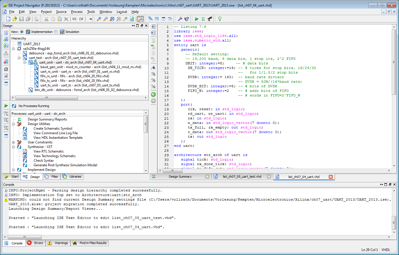
Choose View: Implementation: Synthesis - XST: Generate Post-Synthesis Simulation Model
Result File: netgen/synthesis/uart_synthesis.vhdl
The result file contains a description of the UART using FPGA primitives.
These primitives have to be available in the layout.
Vivado
After Synthesis run a command in the 'Tcl Console':write_vhdl <filename>
A VHDL file using UNISIM components is generated.
Analysis of synthesis file modulo_10_counter
Electric_mod_m_counter_synthesis.vhdThe modulo 10 counter has a structural description with primitives:
INV (1), BUFGP (1), LUT3 (1), OBUF(5), IBUF(1), LUT4(3), FDC (4)
After synthesis LTSPICE code for simulation was added to the layout.
.include cmosedu_models.txt
VDD VDD 0 DC 1
VCLK CLK 0 PULSE(0 1 9n 1n 1n 9n 20n)
VRST RESET 0 PULSE(0 1 50n 1n 1n 20n 20m)
.tran 1000n
LTSPICE simulation of the layout shows a working circuit.
| Cell | Count | Function | Inputs | Outputs | Verification status Xilinx, Electric |
| INV | 1 | Inverter | I | O | ok,ok |
| BUFGP | 1 | Clock buffer | I | O | ok,ok |
| LUT3 | 1 | 3 input lookup table | I0,I1,I2 | O | ok,ok |
| OBUF | 5 | Output buffer | I | O | ok,ok |
| IBUF | 1 | Input buffer | I | O | ok,ok |
| LUT4 | 3 | 3 input lookup table | I0,I1,I2,I3 | O | ok,ok |
| FDC | 4 | D-flip-flop | C, D, PRE | Q | ok, ok |
Test of primitives
Verification is done in Xilinx Webpack with: basic_primitives_test.vhdVerification is done in Electric with sclib.jelib cells: Sim_LUT2, Sim_Rest running a LTSPICE simulation.
| Cell | Function | Inputs | Outputs | Verification status Xilinx, Electric |
| MUXCY | Multiplexer | CI, DI, S | O | ok,ok |
| XORCY | Xor function | CI, LI | O | ok,ok |
| FDC | D-flip-flop with clear | C, D, CLR | Q | ok,ok |
| FDCE | D-flip-flop with clear, clock enable | C, CE, D, CLR | Q | ok,ok |
| FDP | D-flip-flop with preset | C, D, PRE | Q | ok,ok |
| IBUF | Buffer | I | O | ok,ok |
| OBUF | Buffer | I | Q | ok, ok |
| MUXF7 | Multiplexer | I0, I1, S | O | ok, ok |
| MUXF5 | Multiplexer | I0, I1, S | O | ok, ok |
| BUFGP | Buffer | I | O | ok, ok |
| INV | Inverter | I | O | ok, ok |
Simulation results of primitives
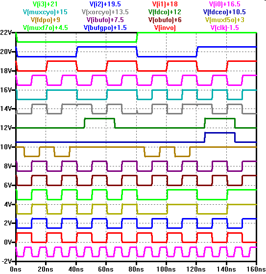
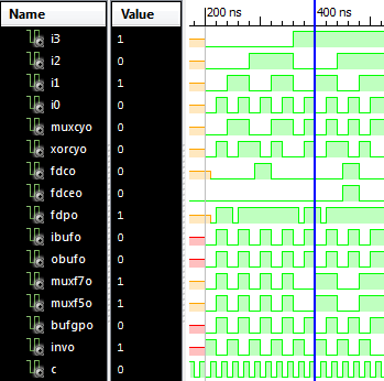
The output matches for all input signal combinations.
Analysis of synthesis file UART
Structural description with primitives:| Cell | Count | Function | Inputs | Outputs | Verification status Xilinx, Electric |
| LUT3_L | 3 | 3 input lookup table | I0,I1,I2 | O | ok,ok |
| LUT2_L | 3 | 2 input lookup table | I0,I1 | O | ok,ok |
| LUT3_D | 2 | 3 input lookup table | I0,I1,I2 | O | ok,ok |
| LUT4_D | 10 | 4 input lookup table | I0,I1,I2,I3 | O | ok,ok |
| LUT2_D | 2 | 2 input lookup table | I0,I1 | O | ok,ok |
| LUT4_D | 16 | 4 input lookup table | I0,I1,I2,I3 | O | ok,ok |
| INV | 23 | Inverter | I | O | ok,ok |
| BUFGP | 1 | Clock buffer | I | O | ok,ok |
| LUT1 | 1 | ???? | I | O | ok,ok |
| OBUF | 21 | Output buffer | I | O | ok,ok |
| IBUF | 3 | Input buffer | I | O | ok,ok |
| LUT2 | 13 | 2 input lookup table | I0,I1 | O | ok,ok |
| LUT4 | 3 | 4 input lookup table | I0,I1,I2,I3 | O | ok,ok |
| FDP | 3 | D-flip-flop with preset | C, D, PRE | Q | ok, ok |
| MUXF5 | 26 | Multiplexer | I0, I1, S | O | ok, ok |
| LUT3 | 50 | 4 input lookup table | I0,I1,I2,I3 | O | ok,ok |
| FDCE | 72 | D-flip-flop with clear, clock enable | C, CE, D, CLR | Q | ok,ok |
| MUXCY | 26 | Multiplexer | CI, DI, S | O | ok,ok |
| XORCY | 21 | Xor function | CI, LI | O | ok,ok |
| FDC | 68 | D-flip-flop with clear | C, D, CLR | Q | ok, ok |
| VCC | 1 | power supply | O | ok, ok | |
| GND | 1 | ground | O | ok, ok |
AnalyzeJS.html Javascript
AnalyzeJS.html was written to translate Webpack VHDL to Electric VHDL.The html file contains one example of webpack output inside the HTML text for testing functionality.
All vectors had to be unpacked and type was changed from STD_LOGIC to BIT.
Basic primitives were created for the cells FDC, FDCE, FDP, MUXF5, IBUF and OBUF in Electric.
LUT2, LUT3 and LUT4 are lookup tables which are configured by a generic statement. For LUT2 all 16 variations X"1"..X"F" were created.
Everything was stored in a library for place and route sclib.jelib
LUT3 and LUT4
For LUT3 and LUT4 a number of LUT2 cells can be multiplexed:entity LUT4_0DF0 is port( I0,I1,I2,I3: in STD_LOGIC;O: out STD_LOGIC); end LUT4_0DF0; architecture LUT4_0DF0_BODY of LUT4_0DF0 is component LUT20 port ( I0,I1 : in STD_LOGIC;O: out STD_LOGIC); end component; component LUT2D port ( I0,I1 : in STD_LOGIC;O: out STD_LOGIC); end component; component LUT2F port ( I0,I1 : in STD_LOGIC;O: out STD_LOGIC); end component; component MUX4 port(I0,I1,I2,I3,I4,I5 : in STD_LOGIC;O: out STD_LOGIC); end component; signal y1,y2,y3,y4,O2 : STD_LOGIC ; begin LUT2_1: LUT20 port map (I0,I1,Y1); LUT2_2: LUT2F port map (I0,I1,Y2); LUT2_3: LUT2D port map (I0,I1,Y3); LUT2_4: LUT20 port map (I0,I1,Y4); MUX0: MUX4 port map (Y1,Y2,Y3,Y4,I2,I3,O); end LUT4_0DF0_BODY;The program AnalyzeJS takes care of this.
The generic statement for the truth table is incorporated into the
cell name: '6A' and 2 LUT2s with a multiplexer are used.
entity LUT3_6A is port( I0,I1, I2: in STD_LOGIC;O: out STD_LOGIC);
end LUT3_6A;
architecture LUT3_6A_BODY of LUT3_6A is
component LUT26 port ( I0,I1 : in STD_LOGIC;O: out STD_LOGIC); end component;
component LUT2A port ( I0,I1 : in STD_LOGIC;O: out STD_LOGIC); end component;
component MUX2 port (I0,I1,I3: in STD_LOGIC;O: out STD_LOGIC); end component;
signal y1,y2,O2 : STD_LOGIC ;
begin
LUT2_1: LUT2A port map (I0,I1,Y1);
LUT2_2: LUT26 port map (I0,I1,Y2);
MUX0: MUX2 port map (Y1,Y2,I2,O);
end LUT3_6A_BODY;
Electric
Start ElectricLoad new sclib.jelib with primitives.
Create new uart library.
Create new uart vhdl cell and insert text.
- Copy all LUT entities into VHDL text
- Copy entity of main uart into VHDL text
- Copy all components into architecture of main uart
- Remove the preset for pins clk, reset, rx in the entity port section
- Remove the ; after the last pin in the entity port section
- Remove entity FDC0, LUT12 and replace LUT12 usage with IBUF
select: the {vhdl} cell
Tools: Silicon Compiler. Convert current cells to layout
For Errors refer to the handout section.
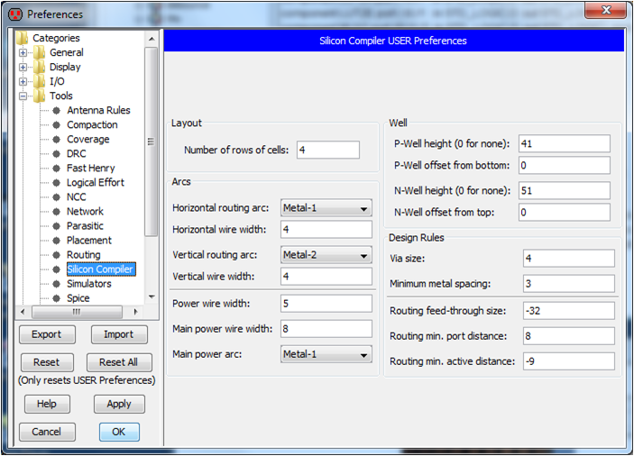
Options can be set in the Preferences menue, Tools, Silicon compiler:
Number of rows of cells: 1..n
Routing feed through size: 12
Routing min. active distance: -9 Cells are placed just to each other
Error message:
=================================20=================================
Reading netlist in cell 'uart_sim{net.quisc}'
ERROR line 27: Cannot find port 'I0' on instance 'LUT2_2'
Line: connect LUT2_2 I0 LUT2_1 I0
Error compiling netlist
Solution: LUT2_2 was a LUT2E. There was a LUT2E{doc.waveform} in this library
Error message:
Generating layout
SC Maker cannot find Horizontal Arc Metal-1 in technology artwork
Solution: Go to a layout cell and select metal 2 line. Try again.
Error message:
SEVERE ERROR - Cyclic conflict to same row, check leaf cells.
Routing feed through size has to be changed.
Change the number of rows. 1 row is always ok.
1,2, 5, 6, 10 rows ok. 3,4 rows bad
Synthesis Results
uart_test: took 1 min 52 sec, area: 77992 x 2351; 1 rowuart_test: took 2 min 4 sec, area: 26880 x 5913; 4 rows
uart_test: took 2 min 15 sec; area: 19456 x 6959; 6 rows
uart_test: took 2 min 49 sec; area: 13650 x 10979 ; 10 rows
uart_test: took 2 min 2 sec; area: 77992 x 2351 ; 1 row conditions changed
A square area is always preferred.
Silicon compiler routing rules:
Default (Best):
Via size: 4, minimum metal spacing 6(3), Routing feed through 16(-32), Routing min port distance 8(8/4), Routing min active distance: 8(-9)
Synthesis Results Layout
Area: 14554 x 7938; 10 rows; Design rules: 4, 3, 32, 8, -9 Tools: DRC: Check Hierarchically: cells ok uart_test takes a long time.
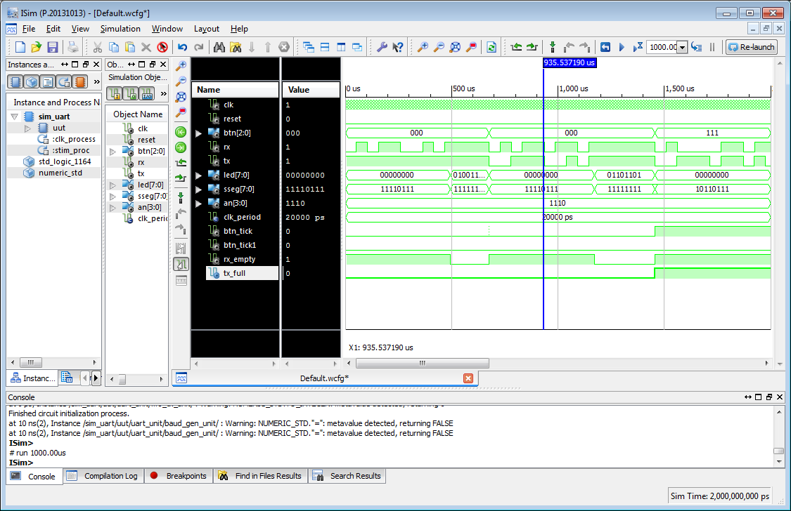
Verification with VHDL Simulation of UART
VHDL test file: sim_uart.vhdInputs are: clk, reset,rx, tx, btn__0, btn__1, btn__2
Outputs are: an__0..3; sseg__0..7, led__0..7
clk has to be 50MHz.
reset is '1' for a short time and is then '0'.
btn__1 needs to be 1 for one clock cycle after data was received.
A seriell input with 19200 baud rate at rx is send with an increment of 1 to tx.
A baud rate of 19200 has 52 us bit duration 0,d0,d1,d2,d3,d4,d5,d6,d7,1.
Simulation time should be 1 ms.
Verification with LTSPICE Simulation of UART
Started LTSPICE 19:58
DC Operation point Newton Raphson Iteration 10 21:28; Iteration 50 06:07
Steppping Gmin 20% 7:39
Implement initial condition for all flip flops:
.ic v(C00)=0 v(C01)=0
No improvement in LTSPICE simulation startup.
2 Days simulation time got no DC operating point.
Conclusion and Outlook
Conclusion
- Success generating a layout from VHDL
- Most area is used with M1 wiring, since only 2 metal layers are available and supported by the routing tool.
- LTSPICE simulation could not be finished.
Outlook
- Investigate impact of routing rules and number of rows on area
- The layout has to be packed into a chip frame with input and output buffers.
- Investigate maximum number of transistors for ralistic LTSPICE simulation time.
| Cell | Subcells | # Transistors | Circuit uart_rx | Circuit serSimpleT4 | uart_test |
| LUT20 | 1 | 47 | 13 | ||
| LUT21 | 4 | 11 | 0 | ||
| LUT22 | 8 | 9 | 1 | ||
| LUT23 | 2 | 4 | 1 | ||
| LUT24 | 8 | 2 | 9 | ||
| LUT25 | 2 | 6 | 4 | ||
| LUT27 | 4 | 3 | 0 | ||
| LUT28 | 6 | 5 | 2 | ||
| LUT2A | 2 | 5 | 5 | ||
| LUT2B | 8 | 1 | 1 | ||
| LUT2C | 2 | 15 | 4 | ||
| LUT2E | 6 | 8 | 2 | ||
| LUT2F | 1 | 19 | 18 | ||
| MUX2 | 12 | 13 | 12 | ||
| MUX4 | 26 | 42 | 14 | ||
| FDCE | 36 | 17 | 0 | ||
| FDSE | 34 | 0 | 2 | ||
| FDRE0 | 36 | 0 | 12 | ||
| BUFG | 4 | 2 | 2 | ||
| OBUF | 4 | 40 | 10 | ||
| IBUF | 4 | 0 | 17 |
serSimpleT4: 1295 Transistors, LTSPICE: 1500ns simulation, 796s (13 min),
MIPS 3000A 115k Transistors
PicoRV32: 750-2000LUTs
LTSPICE option for starting the simulation (2025/05):
.options noopiter srcstepmethod=0 gminsteps=0
Resulting Messages:
Direct Newton iteration for .op point skipped.
Gmin stepping method for .op point skipped.
Starting source stepping with srcstepmethod=0