EEBench 2024
C Serial DAC 2024
Prof. Joerg Vollrath, 13.01.2024
Cost 27.- (2020), R2R DAC, PMOD DA2 20.-, AD2 20.-
|
|
Cost 34.- (2024), C Serial, PMOD DA2 22.-, AD2 30.-
|
Cost 200.- BASYS3 (2024), R2R DAC, MCP6022 OpAmp
|
Status:
Currently NodeEEBench_V2401.zip
is used on a Windows system without including node.js.
NodeEEBench directory is located at C:\temp\
There can be problems with the open statement in ServerEEBench.js (BASYS3) and
ServerAx.js (Arduino)
BASYS 3 project files, bit file and bin file are located in subdirectory NodeEEBench/Xilinx.
EEBench is started with NodeEEBench.bat.
Arduino .ino files for R2R DAC are located in Arduino/DataConverterCharV4.
Arduino .ino files for C Serial DAC are located in Arduino/DataConverterCharV5.
DAC Characterization interface should be started using StartServerAx.bat.
COM port should automatically be detected.
EEBench project overview
A
EEBench github project update is planned,
Here C serial DAC characterization is documented.
+ Overview: Step by step
- Overview: Step by step
- Setting up Arduino environment:
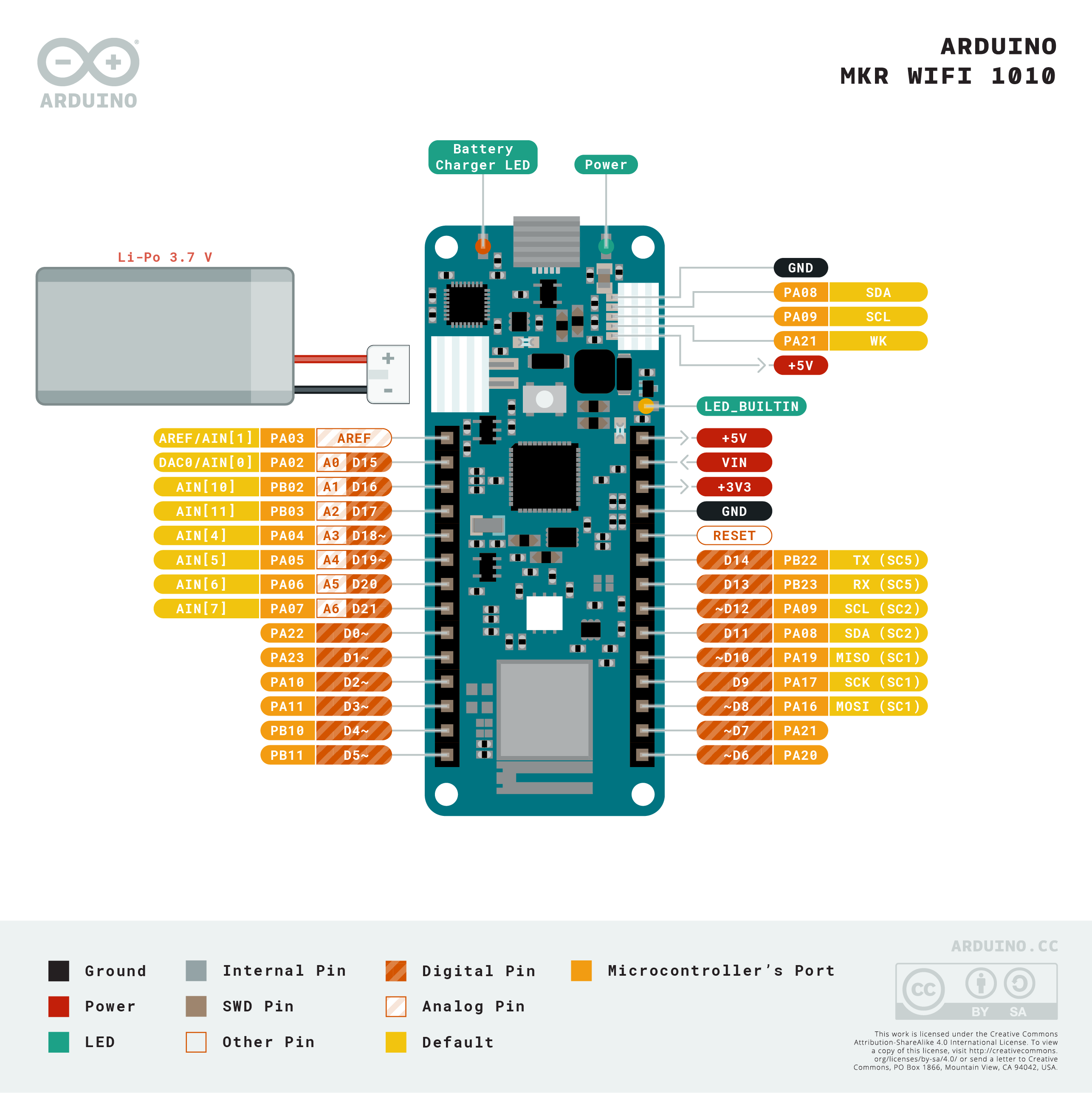
Getting started with the MKR WiFi 1010
Blinking LED
- Realize wiring for
- Arduino DAC and ADC
- C Serial DAC
- PMOD ADC
- PMOD DAC
- Performance investigation
- Ramp data INL, DNL
- Sine data INL, DNL, FFT, SNR
- C change
- Lookup Error correction
- Additional information
- LTSPICE simulation
- Alternative circuit
- Simulate unit element and binary DAC
Pinout MKR WIFI 1010:
+ 1. Setting up Environment
- 1. Setting up Environment
Arduino IDE is already installed in the laboratory.
L:\apps\Arduino click on Arduino
Installation of Win 10 executable.
Zip version is unpacked executable without install? (Device drivers?)
Configuration:
Datei -> Voreinstellung Zusätzliche Boardverwaltung URL's
File ->
URL: http://arduino.esp8266.com/stable/package_esp8266com_index.json
Werkzeuge (Tools) -> Board -> Boardverwaltung ..
Arduino SAMD Boards(32-bits ARM Cortex M0+)
Werkzeuge (Tools) -> Board ->
Arduino MKR WIFI 1010
Connect Board via USB
Set COM port: Werkzeuge -> port -> COM..
Win 10: Gerätemanager -> Anschlüsse
C++ Source code LED blink
Datei -> Beispiele -> 01.Basics -> Blink
Sketch -> Hochladen or "button arrow"
Pfad: Dokumente/Arduino/Work
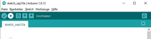
The LED is blinking and everything works.
+ 2. Extension with C serial DAC, ADC and DAC PMODs
- 2. Extension with C serial DAC, ADC and DAC PMODs
Part list
| Part | Number | Cost (Euro) |
| Arduino MKR WIFI 1010 | 1 | 30.- |
| Digilent PMOD AD2 | 1 | 20.- |
| Digilent PMOD DA2 | 1 | 20.- |
| CD4053 switch, MUX | 1 | |
| MCP6022 Rail-to-rail OpAmp | 1 | |
| Capacitances C = 60 pF | 3 | |
| Trim Capacitances C = 4 pF, 6 pF, 8 pF, 40 pF | 1 | |
| Jumper wire (Drähte) | 32 | |
| Micro USB cable | 1 | |
A typical load for MCP6022 according to the data sheet is 60 pF.
CD4053 RDSonmax VDD=5V: 1kOhm
CD4053 Cos = 9 pF
CD4053 Prop Delay 60 ns
CD4053 Prop Delay Time 720 ns
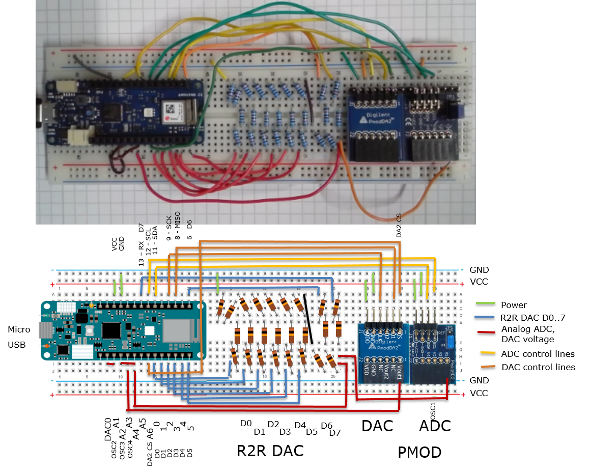
Pin Assignments
- Built in DAC: A0
- PWM DAC: D7
- External DAC PMOD DA2 with SPI interface: CS A6, SCK D9, MOSI D8
- Digital signals for DAC: D0,D1,D2,D3,D4,D5,D6,D13
- 3 ADC as Oscilloscope: OSC2..4, A1..A3
- External ADC PMOD AD2 with I2C interface: SDA D11, SCL D12
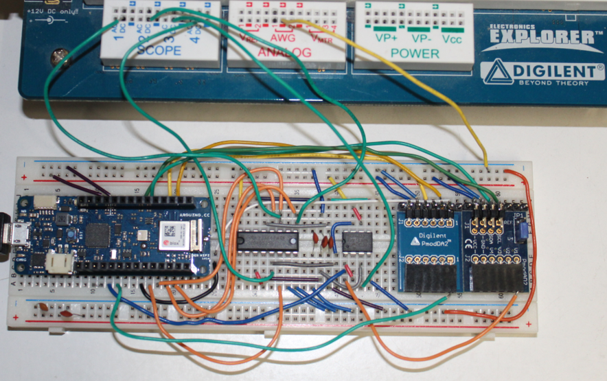
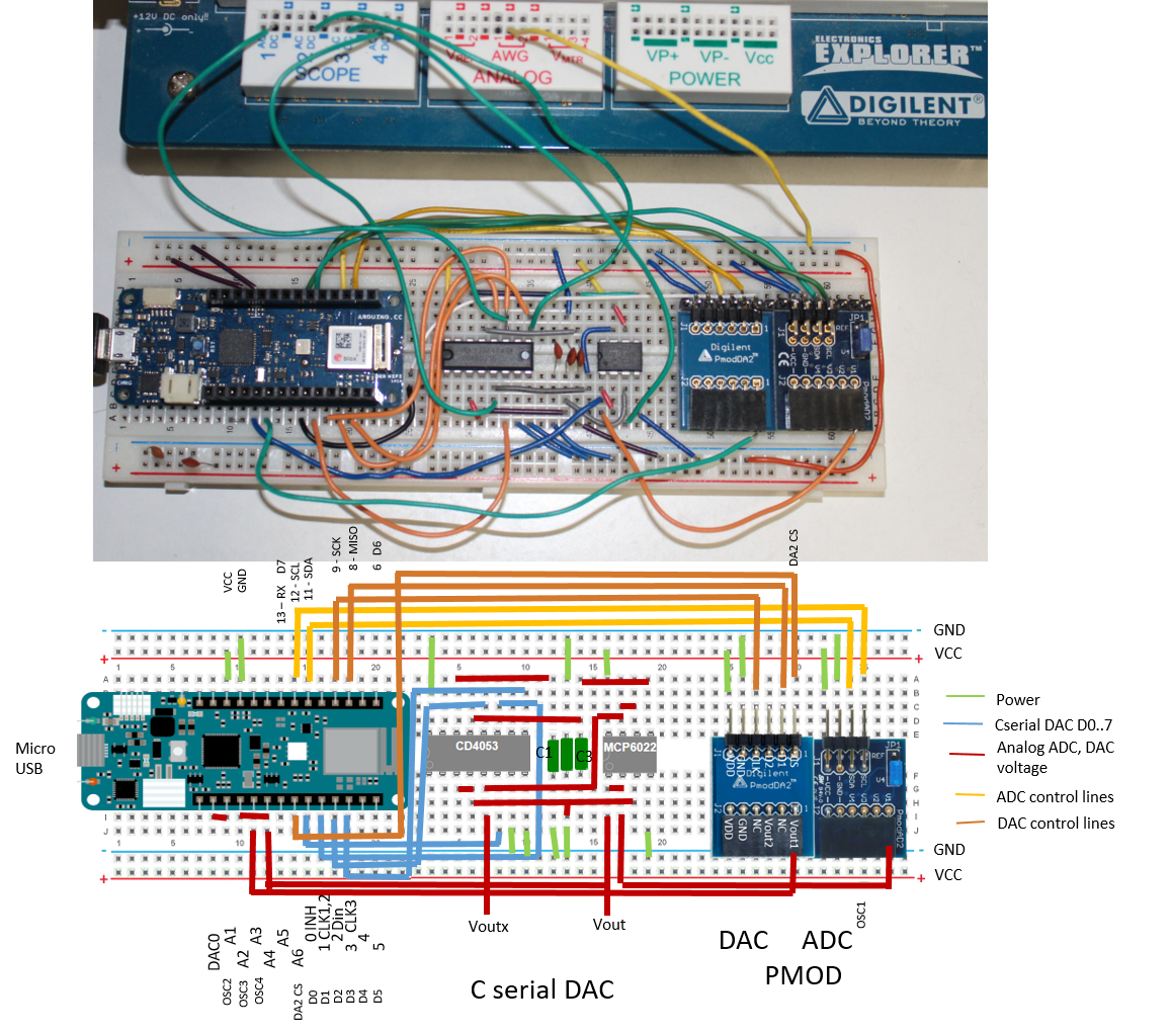
C Serial DAC
Build the C serial DAC on the board.
Wiring list:
CD4053 Pin 16 VDD - 3.3V
CD4053 Pin 7 Pin 8 - GND
CD4053 Pin 6 INH - D0 Arduino
CD4053 Pin 11 A CLK1,CLK2 - D1 (OSC1)
CD4053 Pin 12 AX - C serial data in D2 Arduino (OSC2)
CD4053 Pin 13 AY - C3, MCP6022 pin 5 INB+
CD4053 Pin 14 AC - C1
MCP6022 Pin 8 VDD - 3.3V
MCP6022 Pin 4 VSS - GND
MCP6022 Pin 6, Pin7 - CD4053 Pin5 Cx  (OSC3)
CD4053 Pin3 Pin4 Cy, Cc - C2, MCP6022 Pin 3
CD4053 Pin 9 C CLK3 - D3 Arduino
MCP6022 Pin1, Pin2 - C serial analog voltage out A2 Arduino (OSC4)
PMOD DA2 ( 2 Channel, 12-Bit, 125kHz, 8 µs)
Connect DA2 to the Arduino.
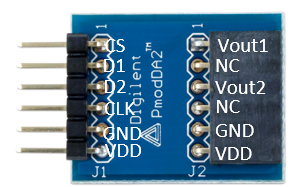
| Pin Arduino | Name | Name | Pin PMOD DA2 |
| D9 | SCK | CLK | 4 |
| D8 | MOSI | D1 | 2 |
| D21 | D21 | CS | 1 |
| GND | GND | GND | 5 |
| +3V3 | VCC | VDD | 6 |
Only Output Vout1 is used for signal generation.
Digilent:
PMOD DA2 20.-
Texas Instruments
DAC121S101 8us settling 12-Bit 16.5 MS/s $1.-
30 MHz SCLK
PMOD AD2
Connect AD2 to the Arduino.
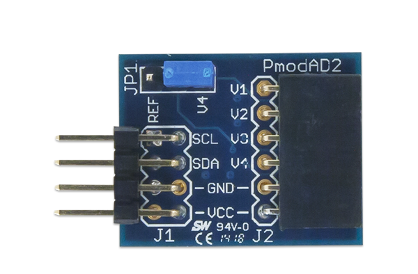
| Pin Arduino | Name | Name | Pin PMOD AD2 |
| D12 | SCL | SCL | 1 |
| D11 | SDA | SDA | 2 |
| GND | GND | GND | 3 |
| +3V3 | VCC | VDD | 4 |
Only Input V1 is used for data acquisition.
Digilent:
PMOD AD2 20.-
Analog devices
AD7991 4 channel, I2C, 1us conversion time, 12-bit
+ 3. Analysis Tool
- 3. Analysis Tool
There is a browser based experimental application available for controlling the Arduino MKRWIFI1010 for
DAC analysis.
Download the sketch DataConverterCharV5.ino to the Arduino.
Program information:
void digWrite(uint16_t sineValue) realizes the C serial write.
var int activeS = 120; // Pulse width of 600 us; 60 gives 300 us
var int nBits = 9; // controls the number of bits
Maximum resolution is limited with sine12 variable.
AWG1: Ideal digital data fed to PMOD DA2 and DAC0/A0 Arduino pin
C1: PMOD ADC
C2: Arduino pin A1
C3: Arduino pin A2
C4: Arduino pin A3
A
NodeEEBench_V2401.zip file containing
nodejs with npm and the HTML and webserver files can be downloaded.
Copy the files into C:\temp. All files should then be in the directory C:\temp\NodeEEBench.
The Arduino needs the sketch: DataConverterCharV5.ino found in the
directory C:\temp\NodeEEBench\Arduino\DataConverterCharV5.
An Internetapplication can than be started by clicking on:
C:\temp\NodeEEBench\StartServerAx.bat
A command window will open starting a internet page. Then the browser should open
the internet address
http://localhost:3000
with the application to control the Arduino board.
At the end of your session please stop the nodejs server with a <STRG>C keyboard entry.
Operation
Waveform Selection
Select a waveform in the waveform generator AWG tab and start the generator 'Run'.
You can see the feed back about the waveform at the configuration tab under the sent command section.
Waveform Acquisition
Change to the oscilloscope tab and click 'Run'. Data is gathered. The Arduino is very slow
and therefore data is slowly gathered and the graph is updated.
Below the graph the running number shows the acquisition process.
Each waveform can be activated or deactivated.
Data can be extracted clicking on the Save button in the oscilloscope tab,
selecting the data and copying them to a text file or into a spreadsheet program.
This data is taken when you click on the button and not updated until again clicking on the button.
The hide button removes the data list.
If the sine waveform is activated a FFT is generated after acquisition of 16k data.
If the triangle waveform is activated a INL, DNL plot is generated after acquisition of 4k data.
FFT tab
Pressing the run button activates FFT display. All selected waveforms
in the oscilloscope window are plotted.
Only FFT of a sine signal makes sense for ADC, DAC Analysis.
A table with signal magnitude and total noise magnitude can be activated by selecting a "Channel".
The number of considered points can be reduced py a power of 2.
Take screenshots for documentation.
Ramp Test INL, DNL tab
By selecting Calculate for Channel and update of the data is initiated.
By default 256 codes in the range of 0 to 255 with step size 1 is considered.
Calculating a best case lookup table can be activated.
Lookup Table
A lookup table can be downloaded to the Arduino.
It has 256 comma separated values in the range from 0..255.
All generated waveform codes will use the lookup table to get a real code for the 8 bit DAC.
The button reset table resets the table to default state without lookup.
Here you can explore different error correction schemes.
Having less codes gives a smaller range and sine wave generator and Ramp Tes range have to be adjusted.
Further Instructions
Please give feedback about the operation of the program.
What is missing in the instructions?
Is anything not working?
Are the calculations correct?
What features are missing?
Please assess severity of these issues.
Are there any benefits or good features of this application?
Do you like this application?
DAC Characterization
- Ramp measurement for INL, DNL
- Settling time with full scale and midscale
- Sine signal FFT SNR
Use ADCs (serial port) and Electronic Explorer oscilloscope input (Export data) for acquiring signals
ADC Characterization
- Ramp measurement histogram for INL, DNL
- Sine signal FFT SNR
Generate ramp with Electronic Explorer AWG1 or PMOD DAC
Use ADCs (serial port) and Electronic Explorer oscilloscope input (Export data) for acquiring signals
+ 4. Additional information
- 4. Additional information
Optimization of Arduino DAC & ADC Resolution
Since Arduino DAC and ADCs are set to 10 bits by default, but their resolution can be increased by accessing them via IDE sketch.
The resolution of Arduino DAC is increased from 10bits to 12 bits by using the code;
analogWriteResolution(bits);
This sketch line is written before the [analogWrite(DAC, sine12);], here sine 12 given as input to let the DAC generate signal that can be tested by 12-bit ADC and then compare with the external 12-bit Pmod DAC. Below is the modified Arduino sketch for optimization of the Arduino DAC.
<!-- Arduino IDE DAC optimization Sketch -->

analogWriteResolution(12);     // Arduino DAC Resolution Change
     analogWrite(DAC, sine12); //  //Writing Analogue to arduino DAC//
Similarly, the resolution of the ADC is increased from 10 bits to 12 and
16 bits. The results of 12-bit optimized combination are realistic and
included in the report. However, it was observed that Arduino MKR WIFI 1010
has maximum accessible resolution of 12 bits, although 65,536 steps
(quantization) were achieved but arduino was padding the extra bits
with zeros. The following addition was made in the sketch before
the serial print argument to increase the ADCs resolution.
<!-- Arduino IDE ADC optimization Sketch -->

analogReadResolution(bits);     // Arduino ADC Resolution Change
Optimization of Arduino DAC & ADC Speed
DMA allows the faster transfer from data to and from the ADC, DAC to memory.
This can speed up waveform generation.
A DAC DMA Exaple was found
here.
Sketch
ZeroDMA_DAC.ino can be downloaded.
Setting the variable period to 199 gives a sine signal with 32 samples at a sample rate of 240 kHz.
The library
Adafruit ZeroDMA
gives an example sketch
ZeroDMA.ino for
reading 256 ADC samples at high speed (2 MHz).
Unfortunately it is difficult to merge the libraries. Change the DAC sampling to ZeroDMA library was not successful.
A general description of SAM DMA can be found
here
.
IRQ with ADC A4 and DAC A0
The sketch
Timer_IRQ.ino
realizes a 15.9 kHz sample rate with an ADC input range of 1..1.65V and DAC range from 0..3.3V.
256 8-bit values are calculated for sine lookup.
ToDo
- Increase DAC samples to 256, 4096 or more
- Increase ADC samples to 4096 or more
- Make a fast synchronous DMA for IOs for R2R DAC
- Elimante ZeroDMA library for ADC DMA sampling and merge sampling and generation
- Making a nice signal generator and oscilloscope interface
- Can more than one ADC input be sampled using DMA?
- Adapting other boards using DMA?
- Use interrupt ISR for ADC reading and DAC writing
YetAnother USB Oscilloscope
Arduino getting stuck and USB device problems
The Arduino can get stuck with infinite loops and IRQ disabled.
Pressing "RST" button twice changes COM address of the Arduino.
Then downloading the Sketch 'Basic' 'Minimum' makes the Arduino again
operational at the previous COM port.
Board not listed in COM Ports
Disconnect breadboard from Arduino and look if the board is recognized.
A short on the breadboard can disable COM port recognition.
Inspect power connections.
Timeline of Realization
- Installing IDE and Blink LED program (1 h)
- Start: 10.09.2020 9:36
- Pictures, Goals (2): 9:57 - 10:07
- Arduino IDE 1.18.13 install: 10:09 - 10:16
- Arduino IDE configure, connect: 10:17 - 10:32
- First program blink LED: 10:40
- Anaolg output DAC, PWM, Digital and 4 ADC input (3 h)
- Analog Read
- Analog Write
8 bit sine lookup table
- PWM write
- Digital pin write
- Extension (3 h)
- PMODs Doku Start Program(14:07-14:16)
- Implement jitter with interpolating external DAC
and changing OSC channel sequence
- Implement ADC, DAC and try out 1h
- Implement ramp and document 1h
- Third Arduino sketch (3 h)
- Resolution and DMA Investigation (6 h)
+ 5. LTSPICE Simulation
- 5. LTSPICE Simulation
+ 6. Alternativ Circuit
- 6. Alternativ Circuit
An alternativ circuit uses an ALD1106, ALD1107 transistor array for the switches.
The TLC272 should be replaced by MCP6022 3 V rail-to-rail operational amplifier.
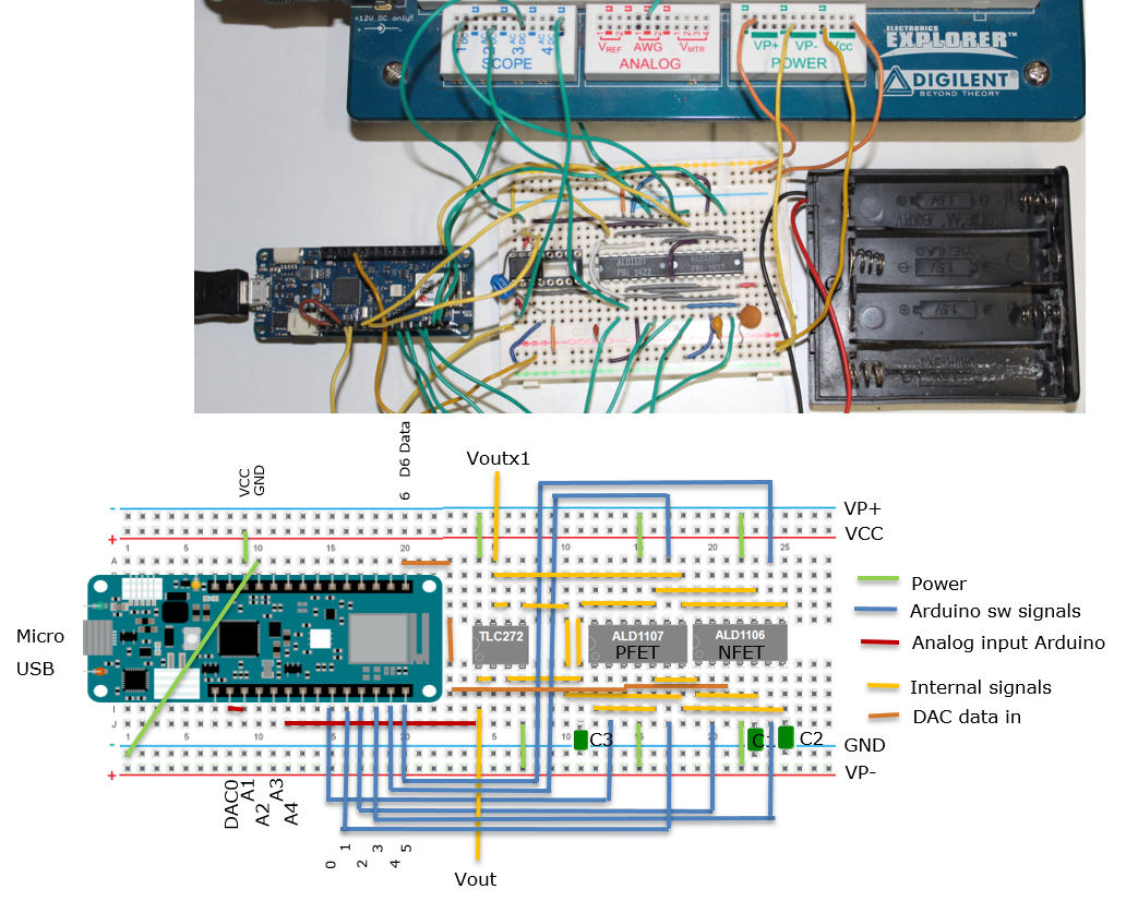
This needs some modifications of the Arduino sketch.
+ 7. Simulate unit element and binary DAC with errors INL, DNL, FFT and SNR
- 7. Simulate unit element and binary DAC with errors INL, DNL, FFT and SNR