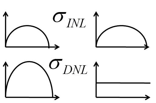
Statistical resistor and capacitor variations: INL and DNL
Switches, opamps and performance
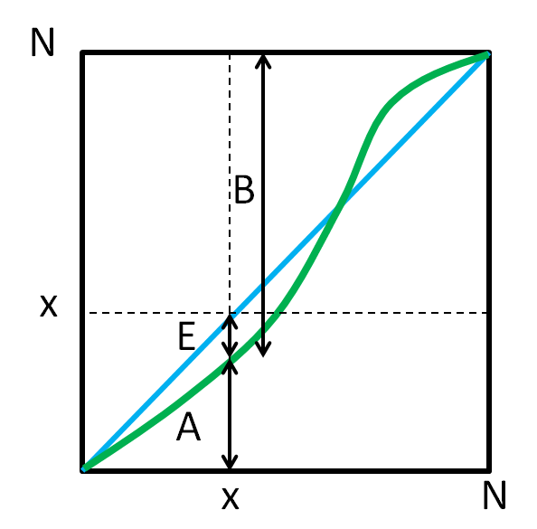
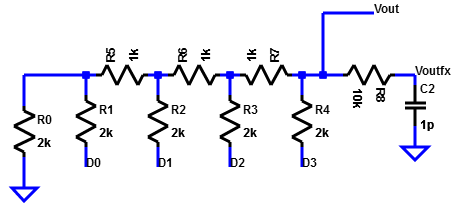
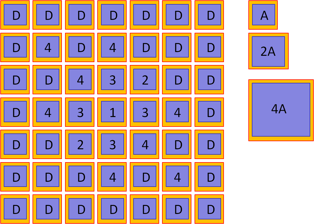
Resistor string DA converter with mismatch
A real 3-Bit resistor string DA converter with Vref= 4V has some error due to R mismatch.
The switches are closed when the control signal is ‘1’. b signals are the inverted signals.
What is the maximum output voltage and the average step size? (3 points)
Fill the table for the transfer function, the INL and DNL ?
Code
000
001
010
011
100
101
110
111
Vout[V]
INL[LSB]
DNL[LSB]
Vmax = Vref/800*700 = 3.5V
LSB = 4V/8 = 0.5V
Code
000
001
010
011
100
101
110
111
Vout[V]
0
0.4
0.9
1.55
2.05
2.55
3.0
3.5
INL[LSB]
0
-0.2
-0.2
0.1
0.1
0.1
0
0
DNL[LSB]
-0.2
0
0.3
0
0
-0.1
0
Limits for DAC scaling
DAC scaling limits
resolution, sample rate, power
DAC architectures
R2R, C2C, ladder, unit element, current source
Resolution
Noise, leakage, mismatch, voltage and temperature variation
Sample rate
RC time constant
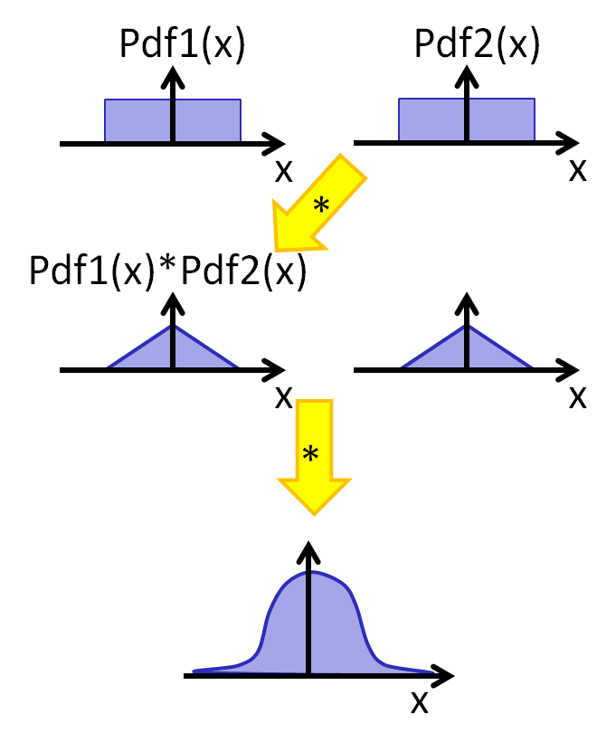
Mismatch and probability density
Real components have random variations
Discrete resistors: 0.1%, 1%, 10%
Integrated resistors: Manufacturing step variations
Model for random variations:
Probability density function
Constant probability of variation.
Mixing of probability functions gives a gaussian distribution
This distribution has no bounds.
The higher the number of components, more components are out of a certain bound.
Manufacturing a resistance or capacitance will also result in variations of value.
This causes INL and DNL errors for data converter and can lead to bad faulty devices.
Width of two, four and six standard deviations have 68.27%, 95.45% and 99.73% of the population.
Realization
In integrated circuits all elements have a gaussian distribution around the designed value.
Since good data converters must meet strict requirements for INL and DNL,
high variations of circuit elements can cause bad INL and DNL.
What variation of circuit elements can be tolerated?
How does mismatch influence INL and DNL?
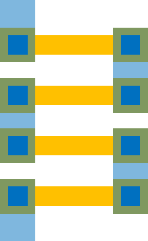
R-string: unit elements
R2R, C2C binary weighted
Example: 0.1% resistor tolerance
Unit element mismatch and DNL
Only random error:
Iref: reference current
Rnom: nominal resistance
C. Lin and K. Bult,
"A 10-b,500-MSample/sCMOS DAC in 0.6mm2,"
IEEEJournal ofSolid-StateCircuits, vol.33, pp. 948- 1958,December1998.
Simulation of 100 runs of unit and binary 10 bit DAC with random variations
with a σεof 2 %.
Plots of INL and DNL showed expected shape of distribution.
RMS of simulation showed the expected values for INL and DNL.
Motivation of segmented DAC with MSB unit elements and LSB with binary weights.
A LTSPICE simulation example with a 3-bit unit element DAC and a 3 and 4-bit binary DAC can be done to
look at DNL and INL error.
Realization of resistors and capacitances
Process variables:
Undercutting
Non uniformities
Unit elements
Ratio area to edge is constant.
Common centroid design
Systematic vertical and horizontal variations cancel out.
Dummy elements
Capacitances
Resistors
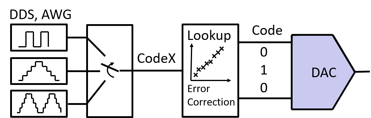
Test and Calibration
Calibration
Element trimming (laser fuse) at the end of wafer fabrication
Inverse equation
Lookup table
Online background calibration
Test and strategy for calibration
Identify topology: unit or binary weighted
Unit elements
Binary weighted elements
Start in the center with biggest error
Laboratory and Calibration
How much can digital calibration do for a binary weighted DAC?
Measure DNL and INL
For big steps in output voltage, DNL large, change capacitances.
Jump at step 64, change capacitances at input D5 with a capacitance
between D4 and D5.
Negative steps or negative DNL create an equation
if (code && 128) { code = code + x }
Create new calibrated input code ramp and measure INL and DNL again.
Create new calibrated input code for sine input signal and measure FFT, INL and DNL again.
Summarize your experience.
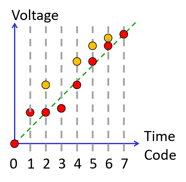
DAC digital calibration example
Code
0
1
2
3
4
5
6
7
Vreal [V]
0
1.5
3
1.8
5
6
6.5
7
Videal [V]
0
1
2
3
4
5
6
7
INL
0
0.5
1
-1.2
1
1
0.5
0
DNL
0.5
0.5
-2.2
2.2
0
-0.5
-0.5
LSB = 1 V
Slope
Reversal
Change
Remove/reorder code 3,6
Adjust step size
DAC digital calibration example result
LSB =1 V
Code range: 0..7
Lookup table, equation
Code
0
1
1
3
2
4
5
7
CodeX
0
1
2
3
4
5
6
7
Vreal [V]
0
1.5
1.5
1.8
3
5
6
7
Videal [V]
0
1
2
3
4
5
6
7
INL
0
0.5
-0.5
-1.2
-1
0
0
0
DNL
0.5
-1
-0.7
0.2
1
0
0
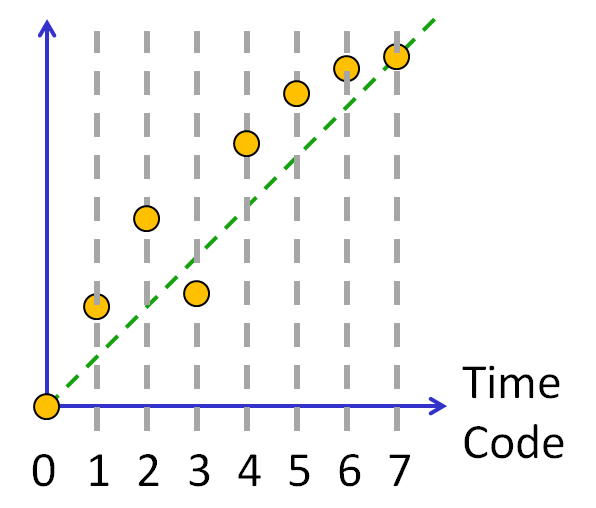
Some codes are very much off the ideal transfer curve (green dotted line).
There is a lookup table placed between the external signal and the internal DAC signal.
For the external Code an internal codeX is generated.
The maximum INL, DNL error of +-2.2 is then reduced to +0.5..-1.
This is still not good enough (below 0.5).
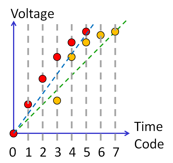
DAC digital calibration example result
LSB =1.4 V
Code range: 0..5
No power of 2!
Lookup table, equation
Code
0
1
2
3
4
5
6
7
CodeX
0
1
2
3
4
5
Vreal [V]
0
1.5
3
1.8
5
6
6.5
7
Videal [V]
0
1.4
2.8
4.2
5.6
7
INL
0
0.07
0.14
0.57
0.29
0
DNL
0.07
0.07
0.43
-0.29
-0.29
The number of used codes (Codex) are now reduced to 5 and mapped to internal 7 codes (Code).
Again INL and DNL is improved.
The maximum INL, DNL error is reduced to +0.57..-0.29.
This is still not good enough (below 0.5).
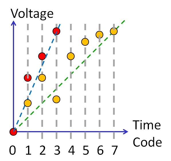
DAC digital calibration: 1 bit reduction
LSB =2.33 V
Code range: 0..3
Lookup table, equation
Code
0
1
2
3
4
5
6
7
CodeX
0
1
2
3
Vreal [V]
0
3
5
7
Videal [V]
0
2.33
4.67
7
INL
0
0.29
0.14
0
DNL
0.29
-0.14
-0.14
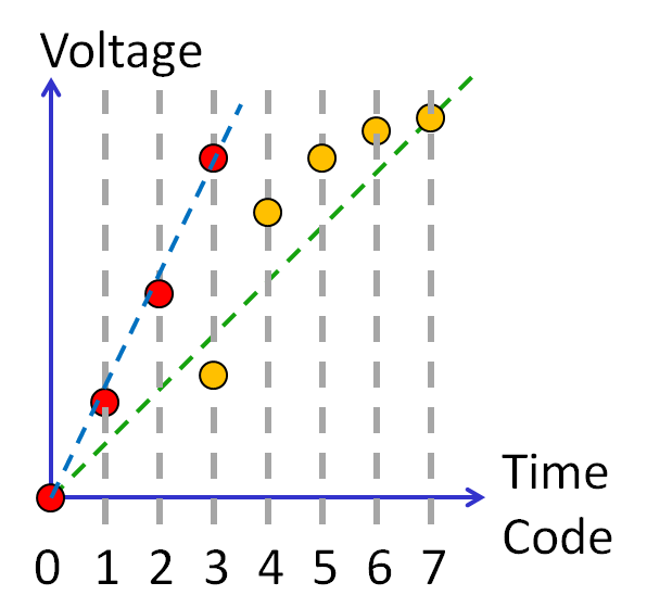
DAC digital calibration: 1 bit reduction
LSB =2 V
Code range: 0..3
Lookup table, equation
Code
0
1
2
3
4
5
6
7
CodeX
0
1
2
3
Vreal [V]
0
1.5
3
6
Videal [V]
0
2
4
6
INL
0
-0.25
-0.5
0
DNL
-0.25
-0.25
0.5
DAC digital calibration summary
Digital calibration is possible.
Lookup table, equation
INL should be in the range of ± 1/2 LSB.
DNL should be in the range of ± 1/2 LSB( ± 1 LSB).
For a power of 2 DAC half the step size, until INL and DNL are smaller than 1/2 LSB.
Otherwise sort the values and identify the biggest step size stepmax.
Depending on the other DNL values the real step size can be between 1.5 LSB = 1.5 stepmax
and LSB = stepmax.
Since numbers are displayed in decimal some codes could be omitted for having
a nice decimal step size: 10 mV, 5mV, 2 mV or a good range.
Binary decimal conversion:
1024 .. 1000
4096...4000
65536..50000
[1] "Nonlinearity analysis of resistor string A/D converters"
S. Kuboki; K. Kato; N. Miyakawa; K. Matsubara
IEEE Transactions on Circuits and Systems
Year: 1982, Volume: 29, Issue: 6
Pages: 383 - 390
[2] "A 10-b,500-MSample/sCMOS DAC in 0.6mm2,"
C. Lin and K. Bult,
IEEEJournal of Solid-State Circuits,
Year: 1998, vol.33, December, pp. 948- 1958