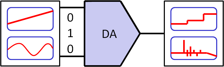
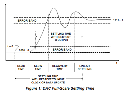
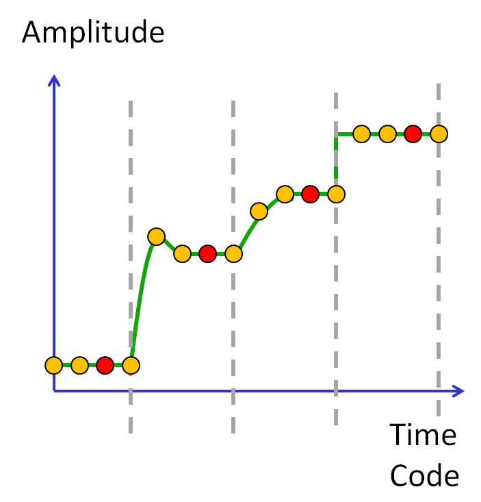
DAC settling time
|
|
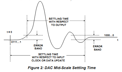
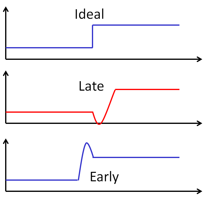
DAC timing glitch
|
|
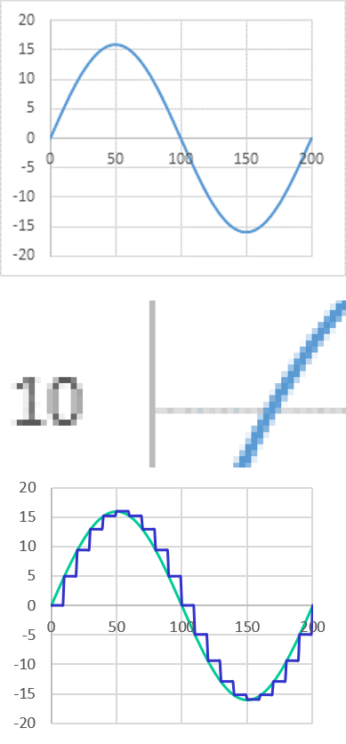
Sampling a sine signal

|
|
A sine function is generated with a x step size of 5.
The output looks like a low bit quantization despite using a very precise floating point number.
The y step size is very big for each step, but can vary a lot.
The output looks like a low bit quantization despite using a very precise floating point number.
The y step size is very big for each step, but can vary a lot.
DAC spectral measurement
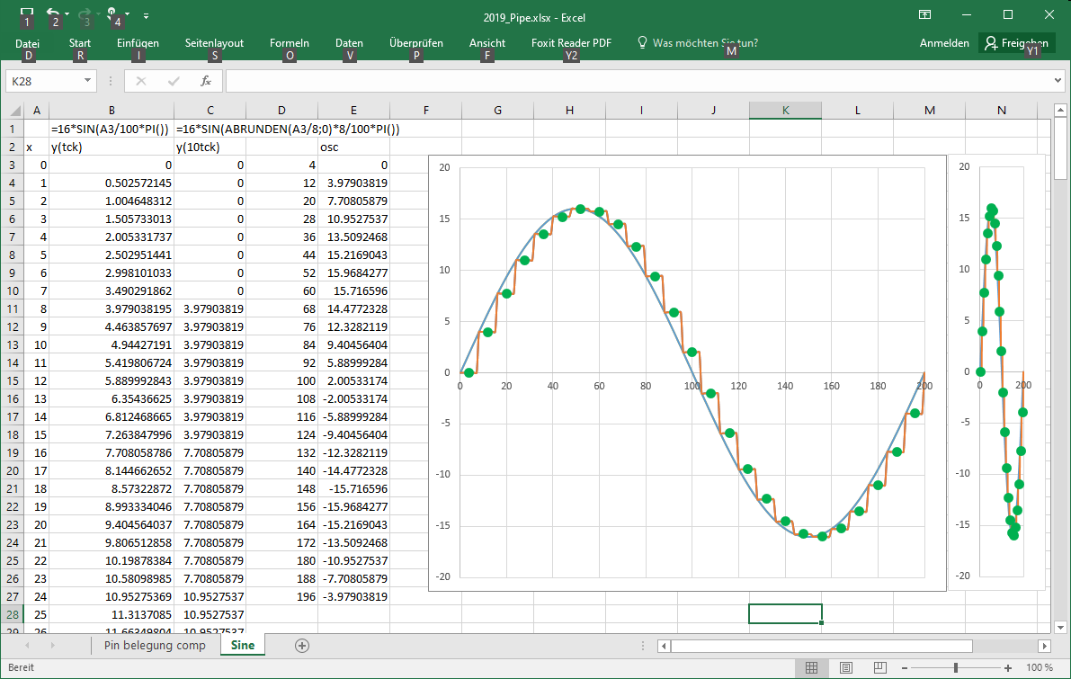
Just sampling in Excel gives a kind of quantization.
DAC spectral measurement
|
|
DAC distortion measurement
Sine signal and FFT10 bit, 11 periods, 2048 points, 16 samples per point
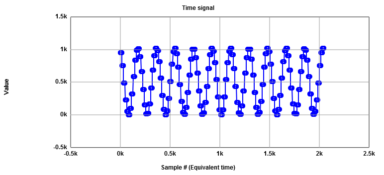
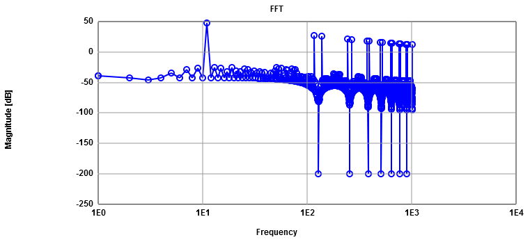
Signal (11) 48 dB, total noise 31 dB (ideal simulation -10 dB)
Harmonics () 27 dB..12 dB
Noise floor peaks -26 dB, total noise -14 dB
You can not estimate levels looking at the graph with reasonable accuracy.
Numerical calculation is required.
10 log (N/2) = 30 dB
Excel:
x, column A: 0..2047 points
y, column B: = RUNDEN(511.5 + 511.5 * SIN(RUNDEN(A2 / 16;0) * 16/2048*11*2*PI());0)
Javascript:
Javascript FFT
x, column A: 0..2047 points
y, column B: = RUNDEN(511.5 + 511.5 * SIN(RUNDEN(A2 / 16;0) * 16/2048*11*2*PI());0)
Javascript:
Math.round(offset + amplitude * Math.sin( Math.round(i/nStep) * nStep / nPoints * nPeriods * 2 *Math.PI()))
Javascript FFT