Interface Electronics09 ADC ArchitecturesProf. Dr. Jörg Vollrath08 ADC introduction, sampling and jitter |
Video Lecture: Flash and SAR ADC
|
Länge: 01:06:27 |
0:2:27 Question 0:2:27 ADC start last lecture 0:3:50 3-bit Flash ADC with R-string DAC with thermometer to binary encoder 0:9:19 Discussion speed, resolution 0:11:19 Thermometer code and binary code 0:13:47 Transistor function encoding binary output 0:15:49 Speed, parallel operation, input capacitance, 0:18:6 Power 0:19:36 LSB and gain = Vdd/LSB, limited bandwidth 0:21:14 Input noise, Voffset 0:24:31 Interpolating Flash ADC 0:28:22 Folding Flash ADC 0:37:19 SAR ADC 0:40:7 Operation example for input 0.6 V with Vref = 1 V 0:49:3 Details of the circuit in LTSPICE 0:52:18 Simulation time |
Review and Overview
- Flash ADC
- Interpolating and folding flash ADC
- Successive approximation (SAR) ADC
A practical example of a SAR
Flash ADC
OperationResolution BSpeedPower | cmosedu_models.txt |
The Flash ADC generates a thermometer code.
For each level one comparator is needed. High count of comparators, high input capacitance.
High resolution requires low comparator offset and high gain to generate a full level digital signal.
The offset of a comparator depends on the size of the CMOS input transistors:
Voffset ∝ \( \frac{1}{\sqrt{W \cdot L}} \)
Lower noise means higher area and higher input capacitance.
If the requirement for comparator offset is not met or noise is present sparkle codes can happen.
The thermometer code is corrupted having more than one transition from 0 to 1.
The code for the first '01' transition is 'OR'ed with the code of the second '01' transition.
Additional digital circuit can be required.
Comparators can feedback noise to the reference voltage ladder. Capacitive coupling between comparator output and intput.
| Thermometer code | Binary Code | ||||||||
| T6 | T5 | T4 | T3 | T2 | T1 | T0 | B2 | B1 | B0 |
| 0 | 0 | 0 | 0 | 0 | 0 | 0 | 0 | 0 | 0 |
| 0 | 0 | 0 | 0 | 0 | 0 | 1 | 0 | 0 | 1 |
| 0 | 0 | 0 | 0 | 0 | 1 | 1 | 0 | 1 | 0 |
| 0 | 0 | 0 | 0 | 1 | 1 | 1 | 0 | 1 | 1 |
| 0 | 0 | 0 | 1 | 1 | 1 | 1 | 1 | 0 | 0 |
| 0 | 0 | 1 | 1 | 1 | 1 | 1 | 1 | 0 | 1 |
| 0 | 1 | 1 | 1 | 1 | 1 | 1 | 1 | 1 | 0 |
| 1 | 1 | 1 | 1 | 1 | 1 | 1 | 1 | 1 | 1 |
For each level one comparator is needed. High count of comparators, high input capacitance.
High resolution requires low comparator offset and high gain to generate a full level digital signal.
| Number of Bits | Maximum Offset | Gain |
| 4 | 0.0625 · Vref | 16 |
| 8 | 0.004 · Vref | 256 |
| 10 | 0.001 · Vref | 1024 |
| 12 | 0.0025 · Vref | 4048 |
The offset of a comparator depends on the size of the CMOS input transistors:
Voffset ∝ \( \frac{1}{\sqrt{W \cdot L}} \)
Lower noise means higher area and higher input capacitance.
If the requirement for comparator offset is not met or noise is present sparkle codes can happen.
The thermometer code is corrupted having more than one transition from 0 to 1.
| Correct code: | 000000011111111 | Encoded binary code | 1000 |
| Sparkle code: | 000000010111111 | Encoded binary code | 1110 |
Additional digital circuit can be required.
Comparators can feedback noise to the reference voltage ladder. Capacitive coupling between comparator output and intput.
Interpolating flash ADC
|
Reduce the number of comparators using interpolation. The output of the preamplifiers are coupled with resistors. |
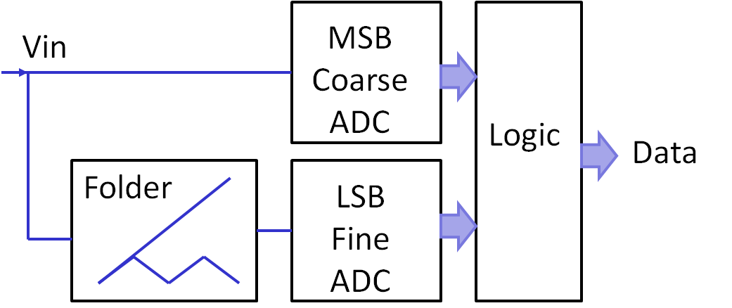
Folding flash ADC
|
Reduce the number of comparators using folding. |
 |
SAR ADC: Blocks
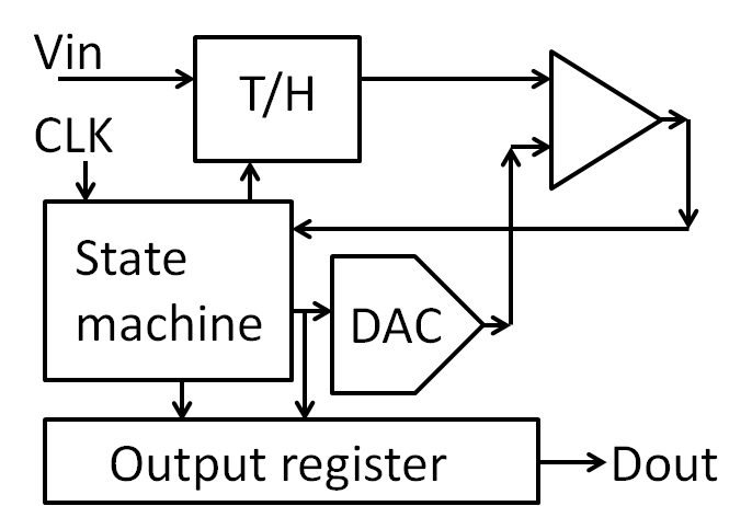 |
At the beginning of the conversion an input signal is sampled.
The comparator compares it with the output of the DAC.
The state machine sets the MSB depending on the outcome of the comparison and then tries the next bit.
The comparator compares it with the output of the DAC.
The state machine sets the MSB depending on the outcome of the comparison and then tries the next bit.
SAR ADC: Flow, Algorithm, Simulation
|
Set MSB to 1: 100000 Loop until LSB set: Compare DAC output with analog input: If DAC output > analog input reset current bit. Try and set next bit. End Loop Blue line shows analog input voltage. Green shows output of internal DAC. Red shows output code with MSB first. |
1 * 0.5 + 0 * 0.25 + 0 * 0.125 + 1 * 0.0625 + 1 * 0.03125 + 0 * 0.015625 + 0 * 0.0078125 + 1 * 0.00390625
0.59765625
SAR ADC: Benefits and Challenges
- Separate blocks can be optimized individually
- Comparator gain and offset:
LSB * gain = Vref
Voffset < LSB
ΔV << LSB: Metastability - Conversion time: n-bits * Settling time
tconv= n * tsettle
Github: 130nm Skywater eFabless 130nm SAR ADC
M. Moser, H. Pretl, "Design of a Low-Power 12-bit Non-Binary Charge-Redistribution SAR-ADC utilizing the SKY130 Open-Source Technology", University Linz, Master Thesis, 2023
References
[1] C. H. Chan, Y. Zhu, S. W. Sin, S. P. U, R. P. Martins and F. Maloberti, "A 5-Bit 1.25-GS/s 4x-Capacitive-Folding Flash ADC in 65-nm CMOS," in IEEE Journal of Solid-State Circuits, vol. 48, no. 9, pp. 2154-2169, Sept. 2013.[2] Behzad Razavi, "Folding and Interpolating ADCs", UCLA
[3] Behzad Razavi, "Folding and Interpolating ADCs", Berkley, 2010
[4] A 700 µW 1GS/s 4-bit Folding-Flash ADC in 65nm CMOS for Wideband Wireless Communications, Nasri,
[5] M.D. Scott,B.E. Boser, K.S.J. Pister, "An ultralow energy ADC for Smart Dust, IEEE J. Solid-State Circuits, pp. 1123-1129, July 2003
Next:
10 Pipeline ADC