Test for 4 Bit ADC and DAC
|
A 4 Bit ADC and DAC test can be simulated in LTSPICE. The files were downloaded and LTSpice simulation was started. The output file size can be limited by using the .save dialog option. A voltage source was added with a ramp from 0 to 1V with a rise time of 655µs. The picture showa ramp input voltages and the DAC ramp output voltage over time 16 steps can be seen with a measurement statement the voltage level were extracted. .Measure TRAN V0000 FIND V(Vout)AT=20u At 60us time the output of 0.0625 V is given for the code 0001. V0001:V0001: V(Vout)=0.0625 at 6e-005 No error in the voltage level can be seen. It is an ideal ADC and DAC. Measurement Codes: .Measure TRAN V0001 FIND V(Vout)AT=60u .Measure TRAN V0002 FIND V(Vout)AT=100u .Measure TRAN V0003 FIND V(Vout)AT=140u .Measure TRAN V0004 FIND V(Vout)AT=180u .Measure TRAN V0005 FIND V(Vout)AT=220u .Measure TRAN V0006 FIND V(Vout)AT=260u .Measure TRAN V0007 FIND V(Vout)AT=300u .Measure TRAN V0008 FIND V(Vout)AT=340u .Measure TRAN V0009 FIND V(Vout)AT=380u .Measure TRAN V0010 FIND V(Vout)AT=420u .Measure TRAN V0011 FIND V(Vout)AT=460u .Measure TRAN V0012 FIND V(Vout)AT=500u .Measure TRAN V0013 FIND V(Vout)AT=540u .Measure TRAN V0014 FIND V(Vout)AT=580u .Measure TRAN V0015 FIND V(Vout)AT=620u 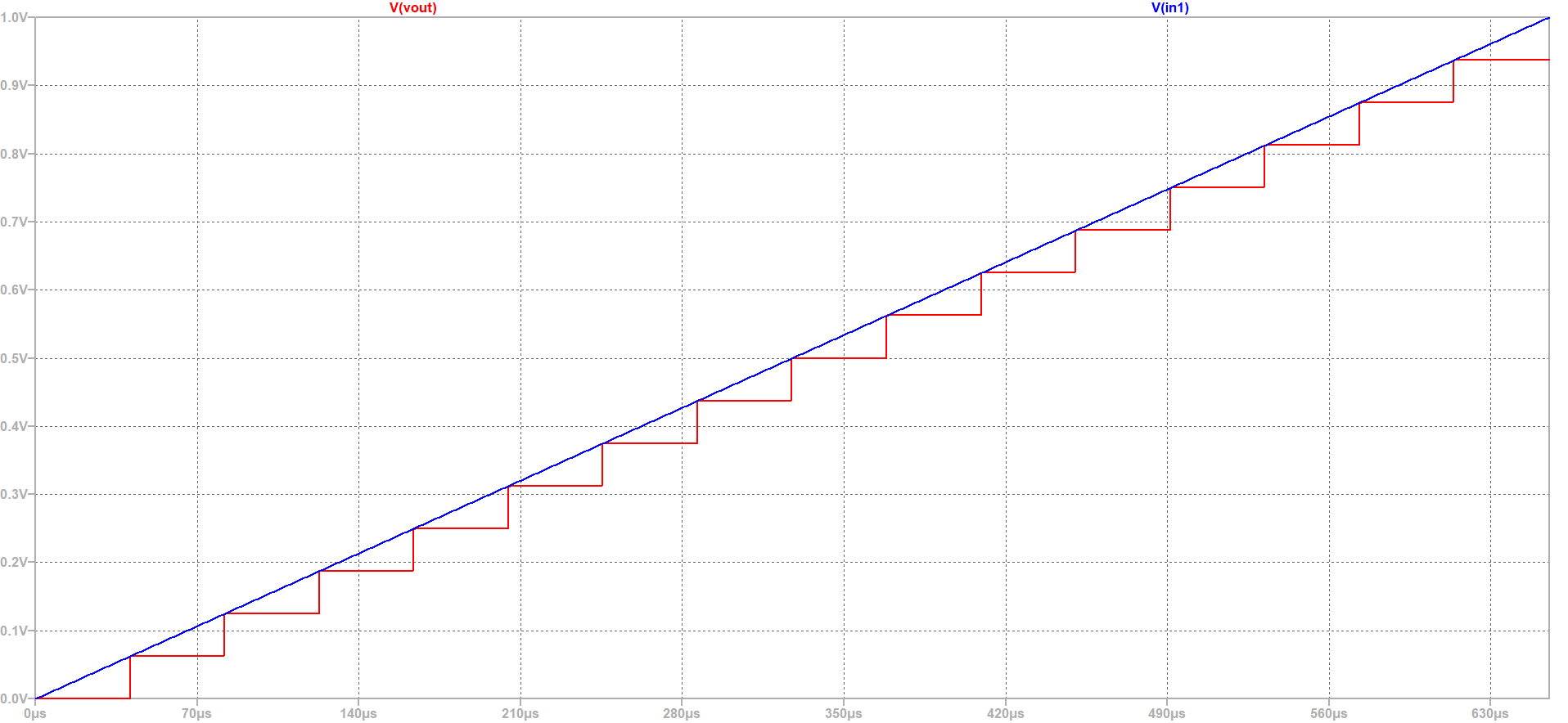 |
LTSPICE schematics
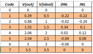 Step size: LSB = V(111)−V(000)/(2^3)−1 = (3.5-0)/7 = 0.5 The step size between 2 successive codes is normalized with LSB and calculated as DNL: DNL(n) = V(n)−V(n−1)−LSB/LSB |