Microelectronics Laboratory2025 Scalable Serial ProcessorProf. Dr. Jörg Vollrath |
Outline
- Motivation and Objectives
- Learn typical steps of a chip design
- Experience an EDA tool chain flow
- Implement a simple function
- Simulate a simple function (Vivado/Verilog, LTSPICE)
- Analyze synthesis results: number of transistors and simulation
- Verilog project and files
- Interface
Input: CLK, CE, RST
Test Interface: Input: TE, TDI Output: TDO
Input: a[3:0] Output: y[3:0] - Simulation
- BASYS3 FPGA Board Implementation
- Chip Design flow
Verilog, VHDL, AnalyzeJSV, Electric, Layout, Padframe
(Tiny Tape out) - Deliverables
A step by step update will be done.
Verilog Project Files
|
Verilog Interface
|
|
Verilog Design Top Module
|
There are 3 instances of modules implemented.
parSer pS0 generates a serial stream at ay0.
serInvSer sIS0 takes ay0 and inverts, delays the stream and gives the stream ay1.
serPar sP0 takes ay1 and converts it to a parallel output at y.
parSer pS0 generates a serial stream at ay0.
serInvSer sIS0 takes ay0 and inverts, delays the stream and gives the stream ay1.
serPar sP0 takes ay1 and converts it to a parallel output at y.
Verilog Simulation Top Module Instances
Instances
|
There are more instances of modules implemented to test all of them.
Verilog Simulation Top Module Vectors(2)
|
There are more instances of modules implemented to test all of them.
Verilog Simulation Result
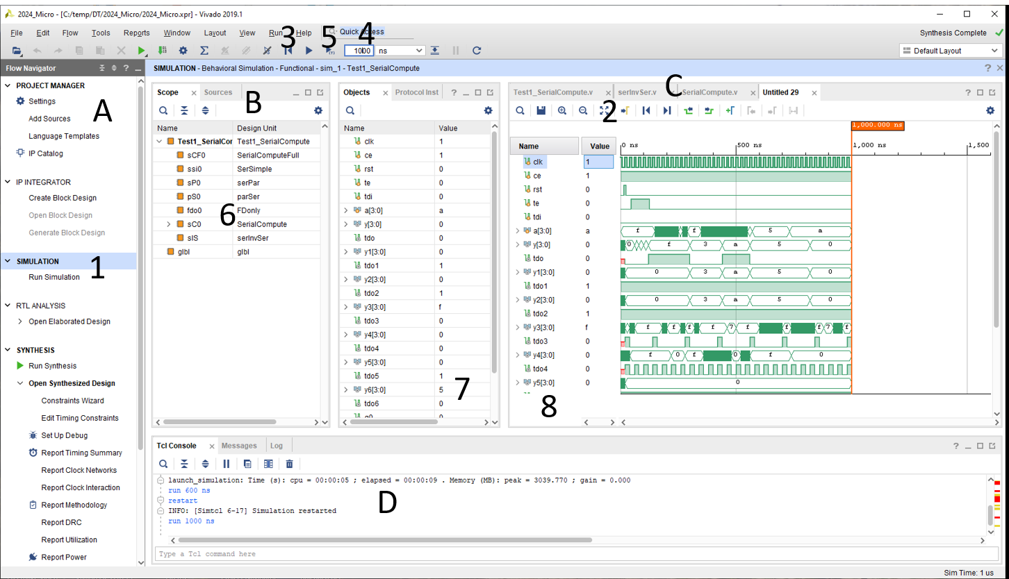
The Vivado environment looks similar to a software IDE and Electric VLSI design system.
(A) lists all design steps: Project, Simulation, Synthesis and Programming
(B) lists all files and configurations
(C) In these tabs files can be edited and results (simulation, implementation are shown.
(D) Contains all messages and errors.
Run Simulation starts the simulation of the top simulation module.
It takes some time until the displayed waveform window appears.
Clicking on (2) fills the window with the complete simulation.
Clicking on (3) resets the simulation.
A simulation time can be put into field (4).
A simulation for this time can be started with (5).
In (6) all available modules are shown. Clicking on the module shows the internal signals (7).
These signals can be added by drag and drop to the simulation window (8), but are only shown after a reset and start of the simulation.
The simulation shows all top signals.
The generated input signals are shown and can be verified and the output signals.
Synthesis and Layout
- Select verilog file to synthesize with 'Set as top'
- Run Synthesis
- Open design
- write structural VHDL to file
write_vhdl <filename>
write_vhdl C:/temp/2025_Micro_JV/SerialCompute.vhd - Open the .vhd file in an Texteditor
- Open the web page AnalyzeJSV.html
- Paste the contents of the .vhd file into the text box
- Push 1. Process VHDL for Electric (Type: BIT)
Hopefully the VHDL is translated for Electric VLSI Design System - Open Electric VLSI Design system and load sclib.jelib
- Copy the resulting VHDL from the web page in section 'Processed output' into a new cell {VHDL} with the name of the top entity in Electric VLSI Design system
- Run Tools, Silicon Compiler, Convert Current Cell to Layout
If errors occur refer to the 08 Systems and VHDL microelectronics lecture. - Add a LTSPICE simulation stimulus to the layout and start LTSPICE simulation.
LTSPICE option for starting the simulation:
.options noopiter srcstepmethod=0 gminsteps=0
Resulting Messages:
Not clear if srcstepmethod=0 or srcstepmethod=1 is better.
.options noopiter srcstepmethod=0 gminsteps=0
Resulting Messages:
Direct Newton iteration for .op point skipped.
Gmin stepping method for .op point skipped.
Starting source stepping with srcstepmethod=0
So far normal solver works best.
Not clear if srcstepmethod=0 or srcstepmethod=1 is better.
Generating LTSPICE input signals
- TestJS.html can be used to generate LTSPICE input signals
- In the input text field put your vectors
Example of 3 vectors for clk, 8 input signals and 5 expected signals:
	ce,rst,te,tdi,a__3,a__2,a__1,a__0;xtdo,xy3,xy2,xy1,xy0;COMMENT
    1,0,0,0,1,1,1,1;0,0,0,0,0;
    1,1,0,0,1,1,1,1;0,0,0,0,0;
    1,0,0,0,1,1,1,1;0,0,0,0,0;
Empty lines at the end cause NaN values in PWL lines. No empty lines!
- The section 'LTSPICE Code' has the PWL voltage sources
for these vectors.
VCLK CLK 0 PULSE(0 1 1e-8 1n 1n 9e-9 10n) Vce ce 0 PWL( 1.0000e-10 1 + 1.0000e-8 1 1.0100e-8 1 2.0000e-8 1 2.0100e-8 1 3.0000e-8 1 3.0100e-8 1 4.0000e-8 1 4.0100e-8 1 5.0000e-8 1 5.0100e-8 1 6.0000e-8 1 ... - LTSPICE simulation should match Vivado simulation
Important LTSPICE simulation commands
.include cmosedu_models.txt
.options noopiter srcstepmethod=0 gminsteps=0
VCLK clk 0 PULSE(0 1 9n 1n 1n 9n 20n)
VCE ce 0 DC 1
vdd vdd 0 DC 1
Vddx vddx 0 DC 1
VGND gnd 0 DC 0
VGNDx gndx 0 DC 0
Vrst rst 0 PULSE(0 1 14n 1n 1n 9n 600n)
Vtdi tdi 0 DC 1
Vte te 0 PULSE(0 1 44n 1n 1n 80n 600n)
* output y__0 y__1 y__2 y__3 tdo
.tran 0 1000n
LTSPICE delay analysis
- Identify VHDL element
- Identify lines and nets in LTSPICE
- Measure delays
A typical VHDL for a LUT3 looks like:
Inputs: net@142, net@150, net@125
intermediate outputs: net@9, net@0
Output: net@58
After simulation the following voltages are plotted giving a nice picture:
Plot: V(net@142)+5.5 V(net@150)+4.4 V(net@125)+3.3 V(net@9)+2.2 V(net@0)+1.1 V(net@58)
Delays are measured for changes of net@58 and the causing change in input signal
Create appropriate .Meas statements and analyze the results.
entity LUT354 is port( I0,I1, I2: in BIT;O: out BIT);
end LUT354;
architecture LUT354_BODY of LUT354 is
component LUT23 port ( I0,I1 : in BIT;O: out BIT); end component;
component LUT24 port ( I0,I1 : in BIT;O: out BIT); end component;
component LUT25 port ( I0,I1 : in BIT;O: out BIT); end component;
component MUX2 port (I0,I1,I3: in BIT;O: out BIT); end component;
signal y1,y2,O2 : BIT ;
begin
LUT2_1: LUT24 port map (I0,I1,Y1);
LUT2_2: LUT25 port map (I0,I1,Y2);
MUX00: MUX2 port map (Y1,Y2,I2,O);
end LUT354_BODY;
..
yi2_i_1: LUT354
port map (
I0 => ddx_reg_n_0_3,
I1 => busy_reg_n_0,
I2 => a_IBUF__0,
O => yi2_i_1_n_0
);
..
LTSPICE will have 3 lines with LU24, LUT25, MUX2
Xyi2_i_1_LUT2_1 net@142 net@150 net@9 gnd vdd LUT24
Xyi2_i_1_LUT2_2 net@142 net@150 net@0 gnd vdd LUT25
Xyi2_i_1_MUX00 net@9 net@0 net@125 net@58 gnd vdd MUX2
Node/network names can be identified:
Inputs: net@142, net@150, net@125
intermediate outputs: net@9, net@0
Output: net@58
After simulation the following voltages are plotted giving a nice picture:
Plot: V(net@142)+5.5 V(net@150)+4.4 V(net@125)+3.3 V(net@9)+2.2 V(net@0)+1.1 V(net@58)
Delays are measured for changes of net@58 and the causing change in input signal
Create appropriate .Meas statements and analyze the results.
Tasks
- Compare LTSPICE simulation and Vivado simulation for SerSimple.v (serPar or parSer)
- Are there errors during synthesis process and can these be fixed?
- What is the optimum number of rows to get a square layout area?
Document the layout - What is the area per transistor in this design and in the subcircuits?
- What is the LTSPICE runtime simduration (error log Total elapsed time:) for which number of transistors and which simlength (.tran command)?
- What is the delay from CLK/input/output for different circuits (table below)?
Can you simulate and extract delay times with 'conservative RC' estimations? - Generate a simulation pattern in Verilog (Vivado) and for LTSPICE for different serial or parallel inputs (table below).
- Is there a maximum number of transistor for LTSPICE simulation?
- Can serInvSer.v be used to implement as starting point for other functions for a stream?
- 2 page final report in IEEE format due 6.7.2025
- Compare LTSPICE simulation and Vivado simulation for serPar.v or parSer.v (SerSimple.v)
Click on the file serPar.v or parSer.v listed under 'Design Sources' in the 'Source' tab and 'Set as Top'.
Run synthesis creates a new structural VHDL - What is the area per transistor in this design and in the subcircuits?
How many transistors are used? - Is there a maximum number of transistor for LTSPICE simulation?
Add more/less instances, synthesize and simulate with LTSPICE
| Input signals | Delay of circuit: | Circuit | ****xx, LF | ||||||
| 0001, 0101 | MUX4, LUT3 | serPar | ******26,MT | ******49,KK | ******34,AM | ******49,DS | ******01,MT | ******03,KJ | |
| 0010, 0110 | MUX2, LUT4 | parSer | ******40,ZS | ******07,LS | ******47,DA | ******86,SN | ******03,TA | ******02,IK | |
| 0100, 1010 | MUX4, LUT5 | serPar | ******97,HL | ******10,NR | ******44,AM | ******36,BN | ******02,SS | ******08,RM | |
| 1000, 0011 | MUX2, LUT3 | parSer | ******89,BF | ******36,KB | ******71,HQ | ******19,RB | ******15,AN | ******34,VM | |
| 1110, 1001 | MUX4, LUT4 | serPar | ******63,PV | ******48,SK | ******09,KM | ******48,BB | ******00,KN | ******47,MS | |
| 1101, 1100 | MUX2, LUT5 | parSer | ******45,EY | ******18,AA | ******40,BB | ******17,BJ | ******08,II | ******50,RS | ******76,BS |
| 1011, 0111 | MUX4, LUT3 | serPar | ******95,BB | ******62,RM | ******86,GB | ******02,MR | ******51,HM | ******63,RS | ******14,HM |
Open Tasks and Issues
- Prepare BASYS3 implementation
switches, LEDs, buttons and configuration - Generate Pad frame