DOI:
Open Access Microelectronics CourseJörg Vollrath University of Applied Science Kempten, Germany Joerg.vollrath@hs-kempten.deAbstractThis paper presents the concepts used for a master class Microelectronics. The course contents are presented as web pages on the internet also for mobile devices. JavaScript enables a Powerpoint like presentation mode, animations, questionnaires and rendering of LTSPICE schematic files on a web page. Only no cost minimum administration tools LTSPICE, "Electric" and ISE Webpack are used for a laboratory to provide open access and enable a chip design. The status of development is shown with an example of a manufacturing process animation, a scan cell design and a synthesis of a UART. Keywords-micro electronics, circuit simulation, open access, SPICE, elearning, JavaScript, HTML |
I. Introduction
Microelectronics is an important topic in electronics engineering. Electronic circuits are evolving using newly available integrated microelectronic circuits. Microelectronics classes are normally provided by universities close to integrated circuit and semiconductor manufacturing industry. Nevertheless many concepts and strategies from microelectronics should be transferred to electrical and electronics engineering. Microelectronics implemented a roadmap strategy to set goals for ever decreasing feature size and higher integration. Integrated circuit product development worked on the principle of providing first any solution and then working on improvements. Simulation and verification of circuits are implemented and are beneficial for the development process of new circuits. Software automation, big data analysis and automated manufacturing like industry 4.0 are employed since the start of microelectronics and are very important to guarantee quality and improve a process. Therefore microelectronics with 90 minutes lecture and 90 minutes laboratory over 14 weeks at the University of Applied Science Kempten is part of the master program 'Electrical Engineering'.
Kempten is located in the south of Germany close to the Stuttgart and Munich area. Bosch, Infineon and Dialog semiconductor are semiconductor companies located nearby. There are also a lot of electronic design automation (EDA) and distribution companies present in the Munich area. The master course is an international course held in English with 15 to 35 students each year. There is only limited funding and manpower available to support this lecture. Therefore an open access no cost approach was used to realize a laboratory and the lecture.
An open access approach for the lecture was used to make it as easy as possible to distribute lecture material and keep it up to date. Presenting all material on a web page makes it accessible from stationary and mobile devices at all times and can be easily found by search engines. The HTML code for the content can be directly updated without having to produce extra pdf files and put them into a content management system like Moodle or on a special file server. HTML and JavaScript also provide means to enrich the pages with equations (MathJS[8]), charts, animations, drawings, pictures, videos and simulations. Examples of features of web pages will be shown first. Emphasized is rendering original LTSPICE schematics on a web page in the next chapter.
Practical examples of a design of a scan cell and a synthesis of a UART with no cost tools are presented next. Challenges for students during laboratory are discussed. Creation of new standard cells and a design flow from VHDL to layout were necessary. The resulting layouts are shown.
Finally a summary and outlook will be provided.
II. MICROELECTRONICS COURSE
The class is structured based on the classic books CMOS VLSI Design, Weste, Harris [1], CMOS Circuit Design, Layout, and Simulation, Baker[2] and CMOS Analog Circuit Design, Holberg[3]. It uses a bottom up approach going from transistor to system on a chip. It has emphasis on automation, simulation, test and verification. Details can be found at the course web page [5].
"Electric" [7] as a design and layout tool was chosen instead of a commercial available system due to no cost and low maintenance. "Electric" is written in Java and can be installed with a local copy of Java. So there is a installation available, which can be copied between systems without having to hassle with the version of java, "Electric" and installation procedures. There is also no license needed making the use in an university environment easy. It is very convenient, where each semester a large group of new students starts to use this tool. Since it is of no cost students can install it on their hardware and use it at home. "Electric" has all basic tools for design and layout except a behavioral VHDL synthesis option. There are design rule checks, layout versus schematic, simulation options and a place and route tool. For simulation LTSPICE can be used. This work shows a way to enable behavioral VHDL synthesis.
LTSPICE is a free SPICE simulator and is used in other lectures at the university. There is no circuit size limited implemented. The size is only limited by the available hardware and simulation time. Documentation options for schematics in LTSPICE are very limited. LTSPICE files are saved with cryptic names. It is very difficult to find a circuit understand the working principle and redo simulations. Therefore it was decided to implement a LTSPICE schematic drawing tool for web pages to improve documentation capabilities and ease of use. A web page can be created displaying all LTSPICE schematics from a directory with filename, comments and annotation.
Enabling synthesis is very important for microelectronics. "Electric" has already a built in silicon compiler taking VHDL code and creating a layout. The VHDL code has to be a structural description without vectors and with the type bit instead of STD_LOGIC. Xilinx Webpack can transform behavioral VHDL into structural VHDL for the used FPGAs. Since this tool was used in a class of digital electronics, it was found out, that it can be used for synthesis of a layout, if the primitives of the FPGA would be present as layout circuits. Therefore a tool was created to transfer structural Spartan 3 FPGA VHDL code to "Electric" compatible code and a library with FPGA primitives was created by the students. A glue script was still needed to change the coding a little bit. To make it easily accessible and maintainable it was written in JavaScript and made publicly available on the internet.
Laboratory starts with MOSFET performance simulation and standard cell layout. Then a CMOS inverter is investigated. These laboratories are guided laboratories with step by step instructions and cover 4 sessions. After that an open laboratory is done covering the rest of the semester with only open instructions. This has the benefit to be able to work on some research topics or create new circuit libraries and tools. In former laboratories a rotary encoder circuit, a scan cell, a pipeline ADC circuit and a GNOME microprocessor were investigated.
All steps as used for a chip design were done by the students during the laboratory in a very limited time frame. At the end the students provided a pdf report about their results. This report is matching a typical engineers report in industry and was used for grading.
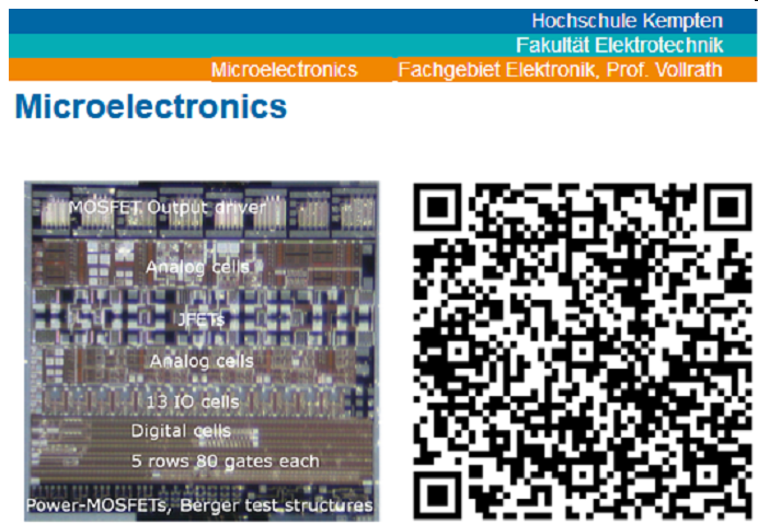
Fig. 1. Microelectronics start web page
III. OPEN ACCESS COURSE WEB PAGE
This work presents an example of open access web pages used for presentation during a lecture and at the same time as script for students. The starting page is shown in figure 1.The QR code enables the students to directly go to the web page using their mobile devices.
There are many examples of course material on the internet as pdf files or HTML text files [1,2,3]. It is very difficult to combine and rearrange this material for a target audience and use it in a class environment. Here a simple JavaScript slide show system S5 [4] was extended for use in electronics engineering class. This systems allows switching a web page from normal outline display mode to a Powerpoint like slide mode. Using native HTML and JavaScript makes the access much faster and provides more features then pdf or Powerpoint. In this context embedded real data can be processed to charts, mathematic equations are listed in LATEX style providing easy copy and paste, animations can be done and interactive web based student response systems can be used. The students can view the material on their mobile phone or laptop during the lecture. Buttons are used to show and hide solutions of given tasks. It is even possible to provide data processing tools like demonstrated in this paper to convert VHDL code from one tool to another input format for the next tool. All files can be copied to a local drive and operated without internet since the JavaScript is executed on the client side.
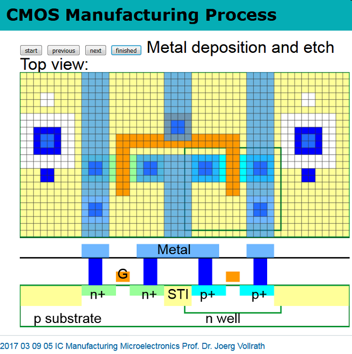
Fig. 2. Animation of a CMOS manufacturing process on a web page
Figure 2 shows the picture of a CMOS semiconductor manufacturing process animation in a slide view mode of the HTML file. The figure shows the final top view and cross section of an inverter. The buttons allow to step through the manufacturing steps. The process starts with active area, followed by well creation, polysilicon gate deposition, source drain formation and finally contact and metallization. Alignment marks are presented on the left and right to discuss problems during pattern transfer. Using JavaScript for animation makes the drawing a little bit more difficult, while providing many options for customization. It is much easier to scale the animation. In a MOSFET transistor animation mobile carrier concentration in the silicon was connected to transfer and output IV curves. This gives the student more insight into the device mechanics.
Schematics in LTSPICE are saved in ASCII files using simple primitives like WIRE, SYMBOL, ATTRIBUTE and TEXT. There are also sub circuits used residing in separate files for the circuit and the symbol. JavaScript provides with jquery.js a simple method to load files and a canvas object to render graphics. In the HTML file first the LTSPICE JavaScript module is loaded. For the actual circuit a canvas is used, a control to set drawing options and some sections for the LTSPICE code are defined. The canvas can be arbitrarily sized to display the schematic properly. Below is typical HTML code for a LTSPICE schematic and figure 3 shows the resulting schematic.
<canvas id="Scan_cell_small_CE" width="300"
height="250"  level="0" class="LTSPICE"
sym="NAND2,TG,INVx,AND2,OR2"> </canvas>
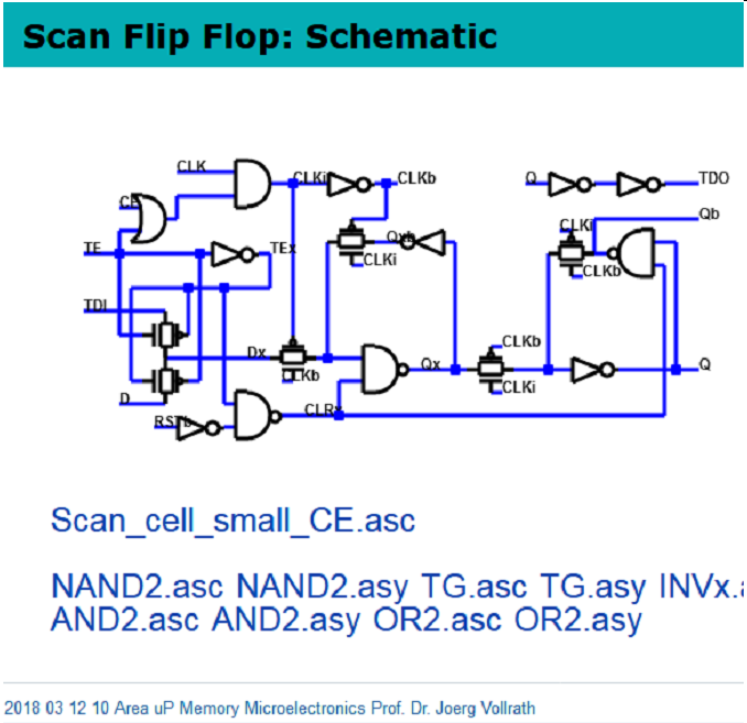
Fig. 3. Scan cell schematic on a web page
The class LTSPICE marks this element for processing. The id is the name of the LTSPICE file in a subfolder LTSPICE and sym is a comma separated list of used symbols. Parameters 'width' and 'height' define the size of the drawing. The extra parameter 'level' defines how much detail is shown in the schematic. LTSPICE text, labels and component names can be hidden using a different level of display. A link is provided for the schematic Scan_cell_small_CE.asc file and the sub circuit files. This makes it easy to download the schematic. For additional files needed for simulation links can also be provided. HTML and JavaScript allows to provide buttons to hide or show this information giving different views. Formatted text can be added on the web page to explain and document the circuit. This allows providing all information while still having a nice dense page layout.
Since this tool is still in development improvements in the user interface are ongoing. It is very easy to copy the webpage to a local drive and modify it. The web page works on the local drive, since JavaScript is executed at the client side. Modifications of the LTSPICE file will be directly displayed at the web page.
More examples using open access web pages can be found on the university web page for the lectures Elektronik 3, Digitaltechnik and Interface Electronics [5].
IV. SCAN CELL DESIGN
Test is one of the important concepts to be able to guarantee functionality of an integrated circuit. Scan cells are modified D-flip-flops with a test enable input and test data in and test data out pins. Unfortunately it is difficult to find a layout of a scan cell. Therefore in summer 2015 the open laboratory dealt with the synthesis of a dynamic scan cell. Starting point was the muddlib library containing flip-flops and logic gates, but no scan cell.
It was interesting to observe the students extending the D- flip-flop to a scan cell. Some students did the design by hand adding additional cells to the provided library primitives and routing by hand.
The other group of students used the silicon compiler to transfer the schematic into layout. Then they shifted the metal 2 connection into the cells by hand. Since there were more connections than space available, some modifications of the base cells were needed to make room for the wiring. Overall the automated approach was faster and made it possible to explore more options than hand routed designs. The automatically routed scan cell was larger than handcrafted cells. A result of an automatic wired cell is displayed in figure 4. It can be seen how M1 horizontal lines were shifted into the cell. Strict rules running M1 horizontal, M2 vertical and using minimum sized transistors enabled successfull design. This is one strategy to reduce complexitiy. Between some cells gaps can be seen due to some overestimation of cell size from place and rout tool.
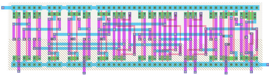
Fig. 4. Synthesized scan cell layout with modified routing
The students compared their results reflecting on similarities and differences.
V. UART EXAMPLE
In summer 2016 the laboratory dealt with the synthesis of a UART. During the laboratory a library of all base cells for synthesis was created by the students. With the library a given VHDL code for a UART was used for synthesis. Since there is no built in tool in "Electric" to do this a new work flow was created (figure 5). Xilinx Webpack was used to map a behavioral VHDL to a structural VHDL description using a limited number of Spartan 3 FPGA primitives. The primitives were flip-flops, multiplexers and 4 input lookup tables (LUT). Flip-flops and multiplexers were available in the "Electric" layout library muddlib. 4 input lookup tables had to be mapped to layout. Instead of creating all 256 possible cells. All 16 possible logic functions for a 2 input logic circuit were created. A 4 input LUT was substituted in VHDL with four 2 input LUTs and a multiplexer. The students had then the task in the laboratory to create these 16 layouts and verify functionality.
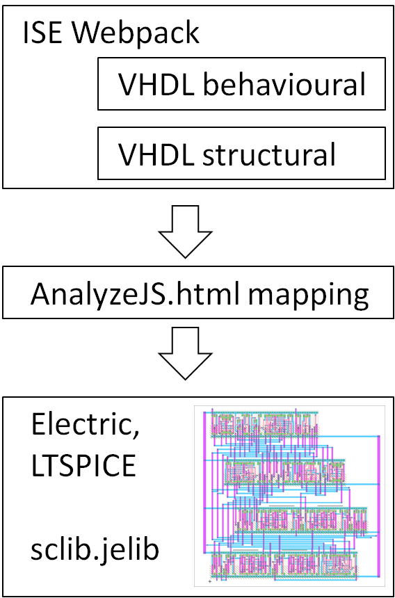
Fig. 5. Synthesis work flow
"Electric" works only with a structural VHDL description without STD_LOGIC_VECTOR and only with the type BIT. Therefore some script code had to be implemented to translate the Xilinx Webpack VHDL file to an "Electric" compatible format. To make this tool easily accessible it was decided to implement it as a web page and use JavaScript for translation. The web page AnalyzeJS.html [9] has an input field where the original VHDL code is pasted. With a button the VHDL is then converted to the desired "Electric" format. Since this is a web page an example VHDL code was embedded into the page to check correct functionality. Additional documentation can also be included in the webpage. Interactive buttons can show and hide this documentation. This web page is on the internet, so everybody can use it, copy it and modify it. This realizes open access.
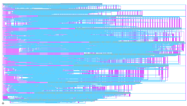
Fig. 6. UART synthesized layout
The code was successfully transferred to "Electric" and a resulting layout can be seen in figure 6. Since only 2 metal layers are available for routing more area is used for wires than for transistors. The synthesis took between 2 and 3 minutes. Options allowed to set the number of standard cell rows. Different settings could be explored to get a square chip and study the effect on the total area.
It was planned to use a LTSPICE simulation to verify operation. Unfortunately the circuit was too big for LTSPICE to find an operation point. Due to lack of time no switch level simulation using IRSIM was done.
VI. SUMMARY AND OUTLOOK
Open access classes are successfully used at the University of Applied Science Kempten. This paper presents the JavaScript tools and internet web pages for a microelectronics class. This concept makes it much easier for the student to replicate simulations and study microelectronic learning material. For the professor it is easier to maintain and update documentation and results. JavaScript and HTML in this context can provide more tools and functionality than traditional learning material giving a better user experience and a more effective learning environment. This was demonstrated with the VHDL processing tool AnalyzeJS and the process animation example. Web pages with schematics make it possible to document circuits and results completely.
In this environment it was possible to do a layout synthesis of a UART at no cost and with minimum man power. The web pages provide detailed instructions. No cost tools ("Electric", LTSPICE, Xilinx Webpack) could be combined with some JavaScript code and a small cell library to get this result. Final verification of the resulting circuit with simulations using IRSIM has still to be done. Changing all library cells to use unit sized transistors is also an ongoing activity.
In the future it is planned to improve the LTSPICE display and implement the functionality to display layouts from "Electric" directly in a web page. Having basic JavaScript routines for layout makes it possible to improve cell layout, routing for more than 2 metal layers and routing in a chip frame. Finally a chip has to be manufactured using these tools.
REFERENCES
[1] Neil Weste, David Harris, CMOS VLSI Design, Pearson, www.cmosvlsi.com
[2] R. Jacob Baker, CMOS: Circuit Design, Layout, and Simulation, Wiley, www.CMOSedu.com
[3] P. E. Allen, D.R. Holberg, CMOS Analog IC Design, http://www.aicdesign.org/scnotes10.html
[4] S5: A Simple Standards-Based Slide Show System, https://meyerweb.com/eric/tools/s5/
[5] J. Vollrath, University person page
[6] J. Vollrath, Microelectronics, https://personalpages.hs-kempten.de/~vollratj/Microelectronics/Vollrath_Micro.html
[7] Electric, http://www.staticfreesoft.com/index.html
[8] MathJS, mathjs.org
[9] J. Vollrath, AnalyzeJS, https://personalpages.hs-kempten.de/~vollratj/Microelectronics/AnalyzeJS.html

| Dr. Ing. Joerg E. Vollrath received 1989 his Dipl. Ing. and 1994 his Ph. D. in electrical engineering, semiconductor technology at the University of Darmstadt, Germany. Since then he worked for the memory division of Siemens and Infineon Technologies and Qimonda in various locations in the USA and Germany. He is now a Professor for Electronics at the University of Applied Science, Kempten, Germany. His expertise and interest lies in the field of design of analog and digital circuits, programmable logic, test, characterization, yield, manufacturing and reliability. He has published 30 papers and has currently 32 patents. |