Digitaltechnik07 Zeichen und CodesProf. Dr.Jörg Vollrath06 VHDL Test und Multiplexer |

|
Ein kurze Videozusammenfassung der Vorlesung
Länge: 6:32 min
Wiederholung und Heute
- Typ: STD_LOGIC
- Ports, Busse und Signale
- VHDL-Testbench und process
Heute:
- Ganze Zahlen
- Festkommazahlen, Gleitkommazahlen
- Rechnen mit Zahlen
- Codes: ASCII, UTF, Gray Code, Thermometer Code
Motivation:
Wie kann ich komplexe Probleme abbilden?
Wie werden Zeichen, Wörter und Zahlen dargestellt?
Überblick, Zahlendarstellung, Codes
- Digitale Systeme: Diskrete Werte
- Logische Pegel und Spannungen
- Ganze Zahlen (Binär codierte Dezimalzahlen BCD-Code)
- Zweier Komplement
- Vorzeichen, Betrag
- Festkommazahlen, Gleitkommazahlen
- Rechnen mit Zahlen
- Codes ASCII Code: Zeichendarstellung Gray Code, Thermometer Code
Zahlendarstellung
Ganze Zahlen
245
Postiv, negativ
Beispiel: D = 12310 = 1 * 100 + 2 * 10 + 3 * 1
Rationale Zahlen
Festkommadarstellung
1.2345
Gleitkommadarstellung
-1.2345E-12
Stellenwertsystem
Zahlensystem: Stellenwertsystem, Positionssystem oder polyadisches ZahlensystemDie Wertigkeit eines Symbols hängt von seiner Position ab.
Dezimalsystem, Dualsystem, Hexadezimalsystem
Es gibt die Koeffizienten ai und die Basis B.
\(\sum_{i=n} ^{0} a_i \cdot B^i = a_n \cdot B^n + \dotsb + a_2 \cdot B^2 + a_1 \cdot B + a_0 \)
| Dezimalsystem: | B=10; | a = {0,1,2,3,4,5,6,7,8,9} |
| Hexadezimalsystem: | B=16; | a = {0,1,2,3,4,5,6,7,8,9,A,B,C,D,E,F} |
| Dualsystem: | B=2; | a = {0,1} |
JavaScript: 0x z.B. 0x4, 0xA
HTML: Farben z.B. "#00ffbf"
VHDL: x"0AB"
Binäre Zahlen, Dualzahlen
Bit: 0,1- Byte: 8 Bit, 2 Hexadezimalzahlen: 0x4A, Bereich: 0..255
- 10 Bit, Bereich: 0..1023, 1 kBit, 3 Dezimalstellen
(20 Bit, Bereich: 1 MBit; 1 GBit, 1 TBit) - Word: 16 Bit, 2 Byte, Bereich: 0..65535
Über den Stellen wird die Wertigkeit gezeigt.
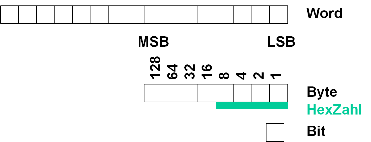
Umrechnungen
Positive ganze Zahlen:| Dezimalzahl | Dualzahl | Hexadezimalzahl | |
| Dezimalzahl | D = bn 2n + ... + b1 21 + b0 20 | D = Hn 16n + ... + H1 161 + H0 160 | |
| Dualzahl | Hexadezimalzahl | Tabelle | |
| Hexadezimalzahl | Teile mit Rest | Tabelle |
Zahlenumwandlung
Umrechnungstabelle
|
|
Umrechnung: Teilen mit Rest
Wiederholtes Teilen einer Zahl Z durch die neue Basis B mit Rest Ri transformiert eine Zahl von einem System zum Anderen.Beispiel Dezimalzahl zu Dualzahl :
Damit es nich zu lange dauert wird erst dezimal zu hexadezimal gerechnet und dann die Tabelle verwendet.
Dezimal: 35783
35783 / 16 = 2236 Rest 7
2236 / 16 = 139 Rest 12 ( C)
139 / 16 = 8 Rest 11 ( B)
8 / 16 = 0 Rest 8 ( 8)
Hexadezimalzahl: 0x8BC7
Anwendung der Tabelle zur Darstellung der entsprechenden Dualzahl:
| Hexadezimalzahl: | 8 | B | C | 7 |
| Dualzahl: | 1000 | 1011 | 1100 | 0111 |
Darstellung negativer Zahlen
Zweierkomplement
|
|
Bei der Bildung des Zweierkomplements, der zugehörigen negativen Zahl, werden alle Bits invertiert und 1 zur Zahl addiert.
Rechnen mit dem Zweierkomplement
|
Bildung einer negativen Zahl: 3: 0011 Invertieren: 1100 1 addieren: 1101: -3 |
Addition: 4 + (-3) = 1
|
Festkommadarstellung
|
|
Gleitkommadarstellung
IEEE-754-Gleitkommaformat
Typ: single, 32 Bit, 4 Byte| 31 | 30 | 29 | 24 | 23 | 22 | 21 | 1 | 0 | ||
| S | E | E | .. | E | E | M | M | .. | M | M |
| V | Exponent | Mantisse | ||||||||
| Vorzeichen, sign | ||||||||||
\( z = (-1)^{V} \cdot 1.M \cdot 10 ^{(E-127)} \)
Dezimalstellen: 7..8
Kleinste Zahl: 1.175 ⋅ 10-38
Größte Zahl: 3.403 ⋅ 1038
Es ergeben sich beim Rechnen immer aufgrund der beschränkten Genauigkeit Rundungsfehler.
https://de.wikipedia.org/wiki/IEEE_754
ASCII Codierung
| Code | …0 | …1 | …2 | …3 | …4 | …5 | …6 | …7 | …8 | …9 | …A | …B | …C | …D | …E | …F |
|---|---|---|---|---|---|---|---|---|---|---|---|---|---|---|---|---|
| 0… | NUL | SOH | STX | ETX | EOT | ENQ | ACK | BEL | BS | HT | LF | VT | FF | CR | SO | SI |
| 1… | DLE | DC1 | DC2 | DC3 | DC4 | NAK | SYN | ETB | CAN | EM | SUB | ESC | FS | GS | RS | US |
| 2… | SP | ! | " | # | $ | % | & | ' | ( | ) | * | + | , | - | . | / |
| 3… | 0 | 1 | 2 | 3 | 4 | 5 | 6 | 7 | 8 | 9 | : | ; | < | = | > | ? |
| 4… | @ | A | B | C | D | E | F | G | H | I | J | K | L | M | N | O |
| 5… | P | Q | R | S | T | U | V | W | X | Y | Z | [ | \ | ] | ^ | _ |
| 6… | ` | a | b | c | d | e | f | g | h | i | j | k | l | m | n | o |
| 7… | p | q | r | s | t | u | v | w | x | y | z | { | | | } | ~ | DEL |
Buchstaben, Zahlen, Sonderzeichen
JavaScript: String.fromCharCode(65) "A"
"ABC".charCodeAt(0) // returns 65
Excel: Code() Zeichen()
https://de.wikipedia.org/wiki/American_Standard_Code_for_Information_Interchange
Internationaler Zeichensatz UTF-8 Kodierung.
https://de.wikipedia.org/wiki/UTF-8
Abkürzung ASCII: Amerikanischer Standard-Code für den Informationsaustausch
Abkürzung UTF-8 (HTML Dokumente): 8-Bit Universal Character Set(UCS) Transformation Format
Das Microsoft Betriebssystem verwendet: UTF-16 Little Endian format.
Weitere Details bei Wikipedia.
Abkürzung UTF-8 (HTML Dokumente): 8-Bit Universal Character Set(UCS) Transformation Format
Das Microsoft Betriebssystem verwendet: UTF-16 Little Endian format.
Weitere Details bei Wikipedia.
Bilder, Zeichen, Sprites, Emoticons
Buchstaben und Zeichen können als 8 x 8 Pixel abgespeichert werden.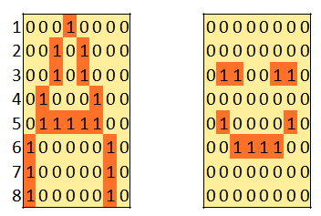 |
Videospiele hatten zu Anfang 8 x 8 Pixel Tiles als Hintergrund und die Figuren sind 16 x 16 Sprites z. B. Pacman 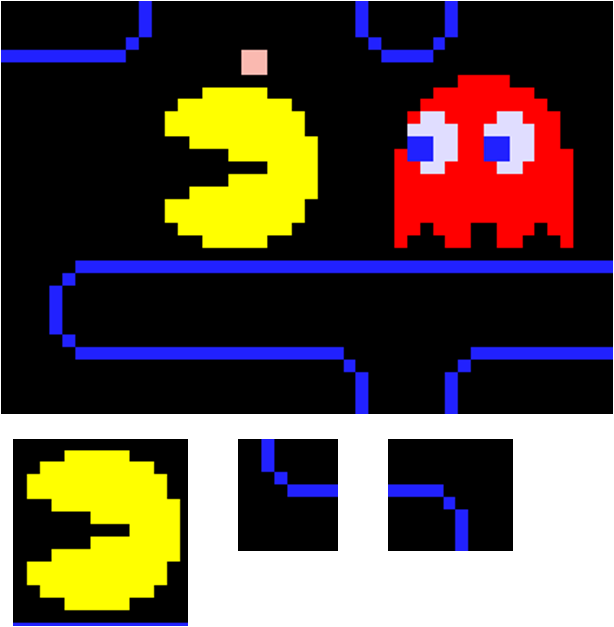 |
Gray-Code und Thermometercode
| Dezimal- zahl |
Dualzahl | Gray Code | Thermometercode |
| 0 | 000 | 000 | 0000000 |
| 1 | 001 | 001 | 0000001 |
| 2 | 010 | 011 | 0000011 |
| 3 | 011 | 010 | 0000111 |
| 4 | 100 | 110 | 0001111 |
| 5 | 101 | 111 | 0011111 |
| 6 | 110 | 101 | 0111111 |
| 7 | 111 | 100 | 1111111 |
Der Gray-Code ist robust und kompakt.
Beim Gray Code wird beim Übergang zwischen zwei aufeinanderfolgenden Codes nur eine Stelle, ein Bit geändert.
Es können nur kleine Fehler auftreten.
Dies ist wichtig bei der Realisierung
Gray-Code Robustheit
Dualcode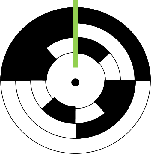 Übergang: 110 -> 101 Zwischenwert: 111 -> 100, Fehlpositionen |
Gray-Code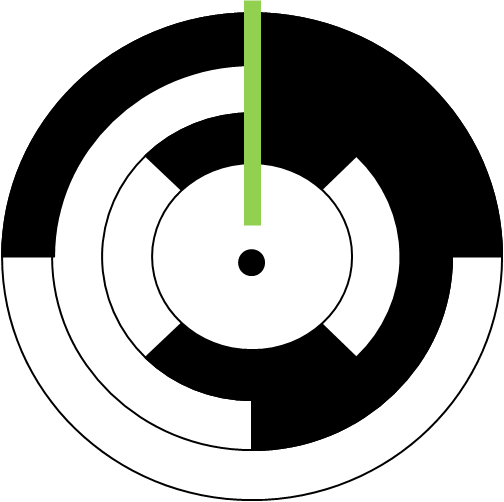 Übergang: 101 -> 111 keine Zwischenwerte möglich, keine Fehlposition |
Eine Codierscheibe kann die Position eines Motors anhand des Codes bestimmen.
Die Codierscheiben sind hier gezeigt. Ein Photodetektor erzeugt eine 0 (weisse Fläche) oder 1 (schwarze Fläche).
7 Segment Anzeige
|
Es gibt eine Konfigurationsdatei (.xdc oder .ucf), die
die Verbindungsdaten eines Schaltungsboards beschreibt. Es wird jedem Pin z.B 'A11' ein Signalname zugeordnet. |
Hexadezimalzahlen auf dem 7 Segment Display. 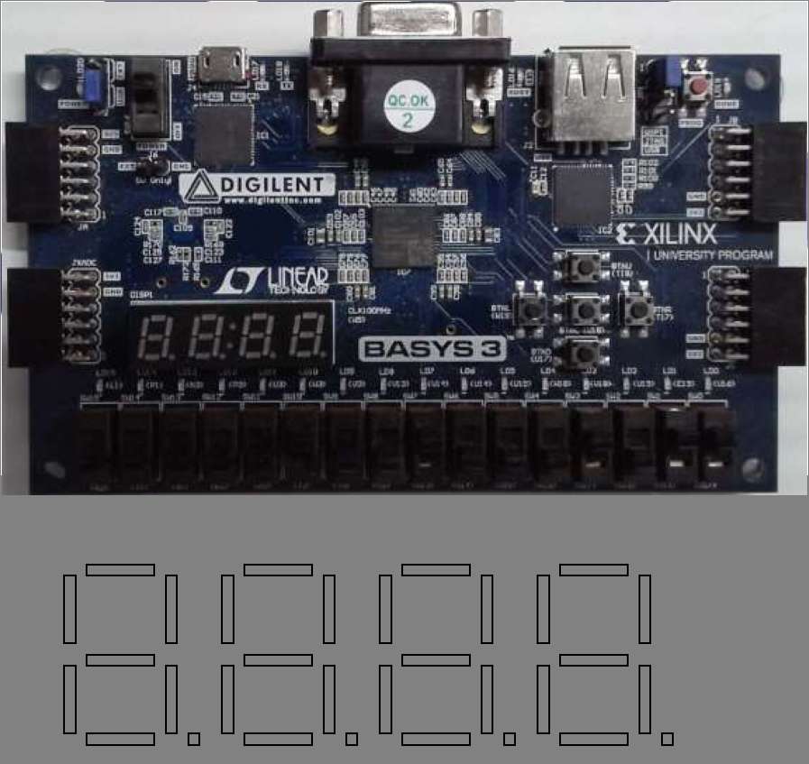 |
7 Segment Anzeige: Hexadezimalzahlen
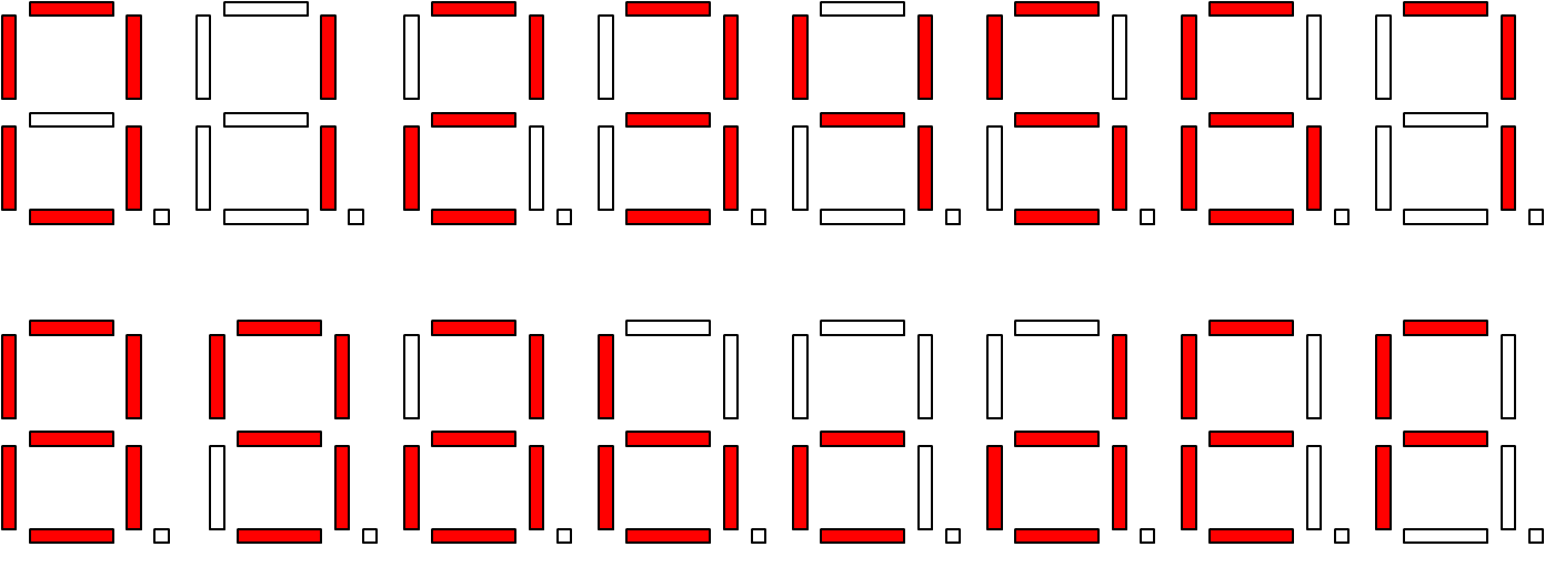
7 Segment Anzeige: VHDL
entity HEX2LEDA is
    port (
        HEX : in std_logic_vector (3 downto 0);    -- HEX input signal
        LEDN: out std_logic_vector (6 downto 0)    -- 7 segment output
         );                                        -- inverted
end HEX2LEDA;
architecture HEX2LEDA_BEHAVE of HEX2LEDA is
signal LED: std_logic_vector (6 downto 0);
begin
  DECODE_P1: process (HEX)  -- process declaration for 7 segment encoding
--  7 Segment: g, f, e, d, c, b, a
--         LED 6, 5, 4, 3, 2, 1, 0
    begin
    case HEX is                                   -- 7-segment decoding
      when "0001" =>    LED <= "0000110";  -- 1   segment encoding:
      when "0010" =>    LED <= "1011011";  -- 2        a
--     ....                                           ---
      when "1110" =>    LED <= "1111001";  -- E    f |   | b
      when "1111" =>    LED <= "1110001";  -- F       ---   <- g
      when others =>    LED <= "0111111";  -- 0    e |   | c
    end case;                                         ---
  end process DECODE_P1;                   --           d
  LEDN <= NOT(LED);  -- concurrent assignment for common anode LED
end HEX2LEDA_BEHAVE;
7 Segment Anzeige: VHDL Praktikum
entity HEX2LEDAX is
    port (
        HEX : in std_logic_vector (3 downto 0);    -- HEX input signal
        LEDN: out std_logic_vector (6 downto 0)    -- 7 segment output
         );                                        -- inverted
end HEX2LEDAX;

architecture HEX2LEDAX_BEHAVE of HEX2LEDAX is
signal LED: std_logic_vector (6 downto 0);

begin
--   segment encoding:
--        a
--       ---                   g, f, e, d, c, b, a
--    f |   | b                6, 5, 4, 3, 2, 1, 0
--       ---   <- g
--    e |   | c
--       ---
--        d
    LED(0) <= ( HEX(3) and not(HEX(2)) and not(HEX(1)) ) or ( not(HEX(3)) and HEX(2) and HEX(0) )
	          or ( not(HEX(2)) and not(HEX(0)) ) or ( HEX(3) and not(HEX(0)) )
	          or ( not(HEX(3)) and HEX(1) )  or ( HEX(2) and HEX(1) ) ; -- a
    LED(1) <= ( not(HEX(3)) and not(HEX(1)) and not(HEX(0)) )
  	          or ( HEX(3) and not(HEX(1)) and HEX(0) ) or ( not(HEX(3)) and HEX(1) and HEX(0) )
	          or ( not(HEX(2)) and not(HEX(0)) )  or ( not(HEX(2)) and not(HEX(3)) ) ; -- b
    LED(2) <= ( not(HEX(3)) and not(HEX(1)) ) or ( HEX(3) and not(HEX(2))  )
	          or ( not(HEX(3)) and HEX(2)  ) or ( not(HEX(1)) and HEX(0) )
			  or ( not(HEX(3)) and HEX(0) ) ; -- c
    LED(3) <= ( not(HEX(3)) and not(HEX(2)) and not(HEX(0)) )
	          or ( not(HEX(2)) and HEX(1) and HEX(0) ) or ( HEX(2) and HEX(1) and not(HEX(0)) )
	          or ( HEX(2) and not(HEX(1)) and HEX(0) ) or ( HEX(3) and not(HEX(1)) ) ; -- d
    LED(4) <= '1';  -- e
    LED(5) <= ( not(HEX(3)) and HEX(2) and not(HEX(1)) )
	          or ( not(HEX(1)) and not(HEX(0)) ) or ( HEX(3) and not(HEX(2)) )
	          or ( HEX(2) and not(HEX(0)) ) or ( HEX(3) and     HEX(1) ) ; -- f
    LED(6) <= ( not(HEX(3)) and HEX(2) and not(HEX(1)) )
	          or ( HEX(3) and not(HEX(2)) ) or ( HEX(1) and not(HEX(0)) )
	          or ( not(HEX(2)) and HEX(1) ) or ( HEX(3) and     HEX(0) ) ; -- g

  LEDN <= NOT(LED);                               -- concurrent assignment
                                                  -- for common anode LED
end HEX2LEDAX_BEHAVE;
7 Segment Anzeige: VHDL Praktikum
Arbeitsauftrag
Erstellen Sie eine Wahrheitstabelle für die Ansteuerung einer 7 Segment Anzeige.
Fragen und Diskussion
|
Rationale Zahlen,Gleitkommadarstellung,BCD-Code,
Word,Byte,Hexadezimalzahl,MSB,
Zahlenumwandlung,Zweierkomplement,ASCII,
Gray-Code, Thermometercode, 7 Segment Anzeige