Elektronik 304 pn-ÜbergangProf. Dr. Jörg Vollrath03 Halbleiter |

|
|
Länge: 00:42:10 |
0:0:0 Oszilloskop XY Diodenkennlinie 0:0:50 Oszilloskop Trigger 0:2:27 Strommessung mit Widerstand 0:4:9 Add XY 0:6:38 Mitschrift Notizen 0:7:42 Leuchtdiode 0:8:14 Eindimensionaler pn Übergang 0:11:34 Poissongleichung Ladungsträger, Feld und Potential 0:13:58 Transportgleichung, Kontinuitätsgleichung 0:14:56 Sperrschichtdicke 0:16:23 Diffusionsspannung 0:20:8 Beispiel Berechnung Diffusionsspannung und Sperrschichtdicke 0:22:18 Math Notepad zur Berechnung 0:26:5 k Boltzmannkonstante 0:27:15 Diffusionsspannung 0.6..1.1 V, Sperrschichtdicke 0:29:10 Höhere Dotierstoffkonzentration kleinere Raumladungszone 0:29:50 Raumladungszone mit externer Spannung 0:31:30 Animation Diodenverhalten Kennlinie, Ladungsträger 0:35:1 Diodengleichung und Kennlinie 0:37:20 Diodenparameter Is, n 0:38:0 Lineare und logarithmische Darstellung 0:42:10 Formula E |
Rückblick und Ausblick
- Was ist Störstellenerschöpfung?
- Welche Dotierstoffkonzentrationen treten bei Halbleitern auf?
- Was ist Rekombination und Generation?
- Welche Ladungsträgertransportströme gibt es und wodurch entstehen Sie?
- Wie ändern sich die Eigenschaften eines Halbleiters mit der Temperatur?
- Warum interessiert uns das Temperaturverhalten von elektrischen Schaltungen?
- Was ist ein Devicesimulator und was kann man damit tun?
Heute:
- Der pn-Übergang, die Diode
Microelectronic, Jaeger: Chapter 3, page: 75-133
LED
  |
|
Die Diode wird mit einem 10kΩ Widerstand verbunden und mit einem Sinussignal mit einer
Frequenz von 0.5 Hz und einer 8 V Amplitude betrieben (Imax = 8 V / 10 10kΩ = 0.8 mA.
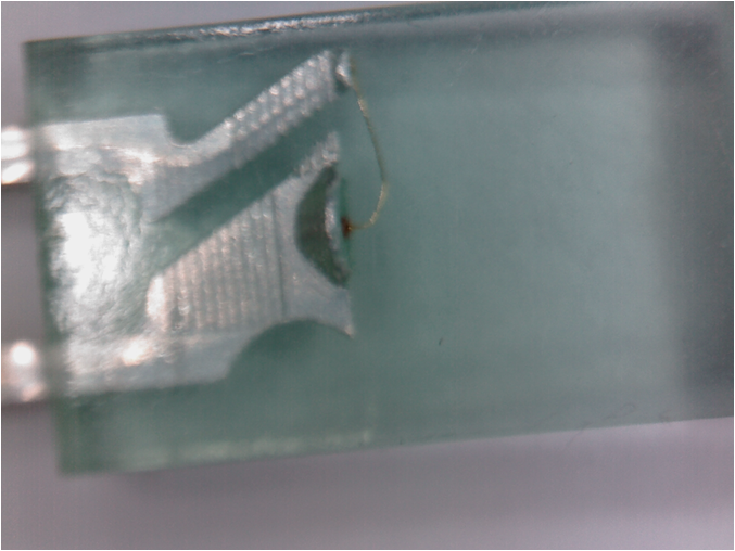
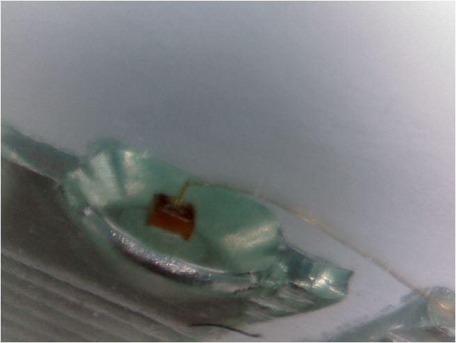
Der kleine Halbleiterblock im Inneren leuchtet bei Stromfluss. Der Halbleiterquader ist in einem Kelch aufgeklebt und
auf der anderen Seite mit einem Draht verbunden.
Die Elektronik (Halbleiterblock) ist viel kleiner als die Mechanik (Anschlussdrähte, transparentes Gehäuse).
Die Elektronik (Halbleiterblock) ist viel kleiner als die Mechanik (Anschlussdrähte, transparentes Gehäuse).
Fragen
- Was passiert, wenn ein n-dotierter und p-dotierter Halbleiter in Kontakt treten?
- Ladungsträgerkonzentration, elektrisches Feld, Potenzial, Spannung und Strom
- Wie sieht die statische Diodenkennlinie aus?
- Strom-Spannungskennlinie, Temperaturverhalten
- Analytische Gleichung
- SPICE Modell
- Wie verhält sich die Diode dynamisch?
- Kleinsignalverhalten
- Schaltverhalten
- Was für Diodentypen gibt es?
Ein pn-Übergang: Diode
|
|
Ein pn-Übergang eindimensional (1)
Kathode: n-dotiert, z.B. Phosphor Version 4 SHEET 1 880 680 SYMBOL diode 32 32 R90 WINDOW 0 0 32 VBottom 2 WINDOW 3 32 32 VTop 2 SYMATTR InstName D1 SYMATTR Value "" TEXT 24 72 Left 2 !Anode TEXT -50 72 Left 2 !Kathode |
Ein intrinsischer Halbleiter 2 dotierte Halbleiter: n- und p-dotiertes Gebiet (ND, NA) Diode: 2 dotierte Halbleiter im Kontakt: n- und p-dotiertes Gebiet Quelle: Vollrath |
Ein intrinsischer Halbleiter hat keine Dotierung.
Die Eigenleitungsladungsträger stehen für die Leitung zur Verfügung.
Bringt man einen n- und p-dotierten Halbleiter in Kontakt, diffundieren die beweglichen Ladungsträger entlang des Konzentrationsgradienten. Feste Ladungen bleiben zurück, die ein elektrische Feld erzeugen.
Im Gleichgewicht sind der Driftstrom (Ladung, Feld) und der Diffusionsstrom (Konzentrationsgradienten) gleich gross.
Die Kästchen mit Plus oder Minuszeichen sind feste Ladungen.
Die Kreise mit Plus oder Minuszeichen sind bewegliche Ladungen.
Der pn-Übergang eindimensional (2)
\( \frac{d(\epsilon_H E)}{dx} = \rho = q(N_D^+-N_A^-+p-n) \) \( E = \int \frac{q}{\epsilon_H} \cdot (N_D^+-N_A^-+p-n) \, \mathrm{d}x \) ohne äußeres Feld: Diffusionsspannung |
|
Poisson-Gleichung: Eine vorhandene elektrische Ladung erzeugt ein elektrisches Feld.
Entlang eines elektrischen Feldes ensteht eine elektrische Spannung.
Entlang eines elektrischen Feldes ensteht eine elektrische Spannung.
Differentialgleichungssystem
- Poissongleichung: U, E
- \( \epsilon_H \) Permittivität des Halbleiters \( \epsilon_{Si} =11.7· \epsilon_0 \)
- \( N_D^+ \) Ionisierte Donatoren
- Transportgleichung \( j_p = q\mu_p p \left(E - V_T \frac{1}{p}\frac{\delta p}{\delta x} \right) \) \( j_n = q\mu_n n \left( E + V_T \frac{1}{n}\frac{\delta n}{\delta x} \right) \)
- Kontinuitätsgleichung
- Die Lösung dieser Gleichungen ergibt:Löcher- und Elektronendichte, Raumladungsdichte \( \rho \), Feldstärke E, Potenzial \( \Psi \)
\( \frac{d(\epsilon_H E)}{dx} = \rho = q(N_D^+-N_A^-+p-n) \)
\( \frac{\delta J_p}{\delta x} = - q \left(\frac{\delta p(x)}{\delta t}-G\right) \) \( \frac{\delta J_n}{\delta x} = q \left(\frac{\delta n(x)}{\delta t}-G\right) \)
Die Transportgleichung besteht aus dem Driftstrom und Diffusionsstrom.
Ausdehnung der Sperrschicht/Raumladungszone (RLZ)
- Neutralitätsbedingung \( N_A·x_p = N_D·x_n \)
- Ausdehnung der Sperrschicht \( d_S = \sqrt{\frac{2 \epsilon_H U_D \left(N_A + N_D \right)}{q N_A N_D}} \)
- Diffusionsspannung UD (Built-in potential)
\( U_D = \frac{kT}{q} ln\left(\frac{N_A N_D }{n_i^2} \right) \)
Temperaturspanung \( U_T = \frac{kT}{q} \)
k: 1.38 · 10-23J/K Boltzmannkonstante
- Wie verhält sich die Sperrschicht und die Diffusionsspannung bei verschiedenen Dotierungskonzentrationen?
εH Dielektrizitätskonstante des Halbleiters
Beispiel: Diffusionsspannung und Sperrschicht einer Diode
Berechnen Sie die Diffusionsspannung und die Sperrschichtdicke (Raumladungszonendicke) einer Siliziumdiode mit NA=1·1017cm-3 und ND=1·1020cm-3.\( \epsilon_{Si} =11.8· \epsilon_0 =11.8·8.85 ·10^{-14}Fcm^{-1} \)
\( q=1.6 ·10^{-19}C; kT/q=0.025V; n_i=1.5·10^{10}cm^{-3} \)
MathNotepad
p-Typ Halbleiter Akzeptor:
\( N_A=1·10^{17}cm^{-3} \)
n-Typ Halbleiter Akzeptor: \( N_D=1·10^{20}cm^{-3}\)
\( U_D = \frac{kT}{q} ·ln\left(\frac{N_A N_D }{n_i^2}\right) = 0.025V ·ln\left(\frac{1·10^{17}cm^{-3}·1·10^{20}cm^{-3}}{1.5·1.5·10^{20}cm^{-6}}\right) = 0.958V \)
\( d_S = \sqrt{\frac{2 \epsilon_H U_D \left(N_A + N_D \right)}{q N_A N_D}} =0.112\mu m \)
NA=1E17
ND=1E20
Esi=11.8*8.85E-14
UT=0.025
ni=1.5E10
UD=UT*log(NA*ND/ni^2)
q=1.6E-19
ds=sqrt(2*Esi*(NA+ND)*UD/q/NA/ND)
Raumladungszone mit äußerer Spannung
- Sperrschichtweite, Raumladungszonenweite
- U äußere Diodenspannung
- Größe: \( U_D – U \gt 0 \)
Sperrrichtung (Spannung U negativ) - In der Raumladungszone kommt es zur thermischen Generation von Ladungsträgern, die vom äußeren elektrischen Feld abgesaugt werden.
- Sehr kleiner Sperrstrom
|
\( d_S = \sqrt{\frac{2 \epsilon_H \left( N_A + N_D \right) \left(U_D-U\right)}{q N_A N_D}} \) |
Bei einer positiven externen Spannung UD wird die Raumladungszonenweite 0.
Bei negativen Spannungen U < 0 V wird UD - U größer und damit auch die Raumladungszone immer größer.
Bei einer Diodenspannung von U = 0 V bleibt die Diffusionsspannung übrig und erzeugt eine Raumladungszone.
Relevanz:
Bei einem realen Bauteil muss Platz für die Raumladungszone im Halbleiter vorhanden sein. Stößt die Raumladungszone an die Anschlüsse oder geometrischen Grenzen kann es zu einem Durchbruch, einem erhöhten Strom im Sperrbereich kommen.
Gerade bei kleinen Geometrieen im nm Bereich ist das eine Herausforderung.
Diode mit äußerer Spannung
|
<---- Diodenspannung ---- 0V |
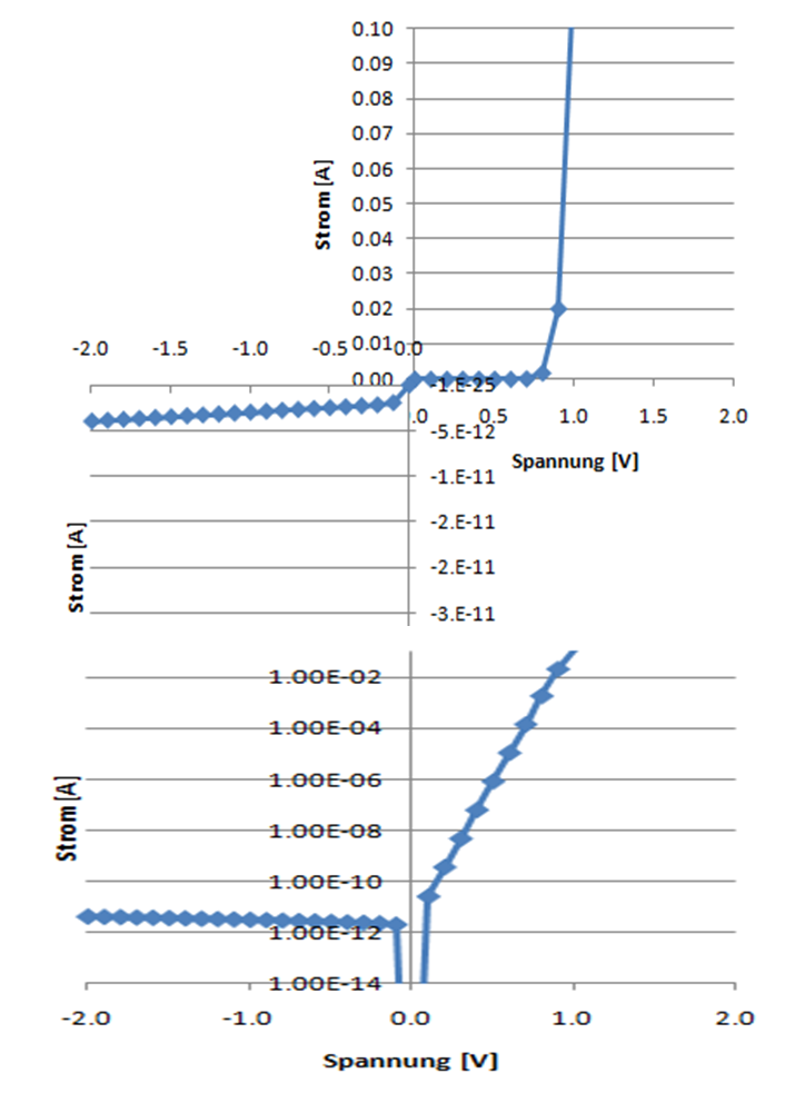
Strom-Spannungskennlinie der Diode
|
 Quelle: Vollrath |
Rückblick
- Differentialgleichungen
- Poisson: U,E (n,p, NA, ND)
- Transportgleichung: Jn,Jp, (E, dn/dx, dp/dx)
- Kontinuitätsgleichung: dJn/dx, Jp/dx, (G, dn/dt, dp/dt)
- Was ist eine Raumladungszone?
- Welche Gleichungen werden benötigt um das Strom Spannungsverhalten eines Halbleiters zu beschreiben?
- Wie lautet die Diodengleichung?
- Wie wird die Weite der Raumladungszone dS berechnet?
- Diffusionsspannung: UD
- Temperaturspannung: \( U_{T} = \frac{kT}{q} = 0.025 V \) für T=300K, Raumtemperatur
Kapazitäten
|
Sperrschichtkapazität (Junction Capacitance)
\( C_S = C_J = \frac{C_{J0}}{\sqrt{1-\frac{U}{U_D}}} \) Es bildet sich eine Raumladungszone mit festen Ladungsträgern. Durch die äußere Spannung wird die Größe der Raumladungszone und damit die Kapazität verändert. Dies wirkt wie ein Plattenkondensator. |
Diffusionskapazität Bei einem Stromfluss befindet sich ein Überschuss an Ladungsträger in der Diode. Bei Änderung der angelegten Spannung verändert sich dieser Ladungsträgerüberschuss. \( C_D = \frac{d(Q)}{dU} = \tau_D \frac{I}{U_T} \) τD: Transitzeit UT: Temperaturspannung |
Schaltverhalten: Einschalten und Ausschalten
|
SPICE Simulation τd Aufladung der Diffusionskapazität Stationärer Strom I1 \( \tau_S = \tau_D ln\left( 1- \frac{I_1}{I_2} \right) \) τS Speicherzeit: Entladung der Diffusionskapazität tf Abfallzeit tf ~ CS(RV+RB) |
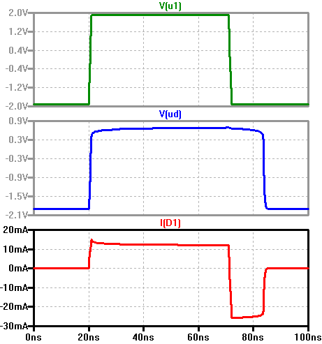 td Stromspitze Einschalten, ts konstanter Gegenstrom, tf Abfall des Gegenstroms |
Für positive Spannung U1 erwartet man einen Stromfluss (12 mA) und für negative Spannung U1
keinen Stromfluss, ein Sperrverhalten.
Beim Abschalten sieht man in der Simulation dennoch für eine gewisse Zeit (ts) einen unerwünschten Sperrstrom (-25mA).
Man kann den Einfluss des Widerstandes R1, der Flussspannung/Flusstrom und der Sperrspannung auf die Stromspitze in Flussrichtung und den Sperrstrom, wie in der Gleichung für τS angegeben untersuchen.
Schaltverhalten: Messung
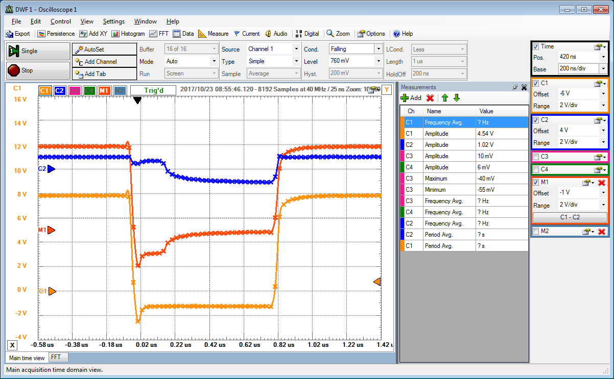
Mittlere Diode aus dem Diodenversuch.
Kleinster Widerstand 100 Ω am Ende des Sockels.
C1 zeigt das Rechteckeingansgsignal zwischen +8 V und -2 V mit einer Frequenz von 500kHz.
C2 zeigt die Diodenspannung.
Ohne eine Speicherladung im pn Übergang, sollte der Strom (M1) durch die Diode bei Sperrspannung sofort Null werden.
Da gespeicherte Ladung vorhanden ist, sieht man noch einen Stromfluss.
Dieses Verhalten entspricht einem Kapazitätsverhalten, man spricht von der Diffusionskapazität.
Nächstes Mal:
- Rechnen Sie die Aufgabe Klausur WS2011: Aufgabe 1
- Variationen der Aufgabe:
Es kann nach der Spannung oder der Dotierstoffkonzentration für eine bestimmte Raumladungszonengröße gefragt werden.
Diodenschaltung