Microelectronics02 HistoryProf. Dr. Jörg Vollrath01 Introduction |

|
Video of lecture 03 24.03.2021
|
Länge: 1:02:33 min |
0:0:54 Transistor, Layout, Cross Section 0:4:5 Transistor count 0:9:5 Moore's Law: Feature Size 0:13:0 Microelectronics over time 0:16:20 iFixit iPhone Analysis 0:18:5 iPhone Main Board 0:19:40 Blessing and Curse of Microelectronics 0:22:48 Design Entry 0:27:5 Software Tools 0:28:35 Integrated Circuit Challenges 0:29:55 Laboratory: Build a 4 bit positive number multiplier 0:32:43 Hierarchical description, one solution 0:36:40 Citations: Don't optimize too early. 0:39:19 Design flow 0:43:25 Technologies 0:47:15 Inverter schematic 0:49:45 Truth table 0:51:13 Source drain, schematic, color, layout box 0:54:5 Stick diagram 0:56:13 What do I do with 1 billion transistors? 0:57:32 Inverter schematic and layout 1:2:5 p-well and n-well 1:5:57 p-well and n-well contact 1:8:31 Layout well contact 1:12:45 F and lambda 1:13:29 N-MOSFET equations 1:16:16 β, width W, length L, capacitance Cox 1:22:4 0 |
Transistor Evolution
 Quelle: Wikimedia 1947 Bell 1 Bipolar transistor 30 μ m 50 MHz |

|
 Courtesy of Intel 2008 Intel Core i7 731 Million MOS Transistors 45 nm process 263 mm2 2.6..3.2 GHz |
It can be seen that the Intel Core i7 has 731 million transistors
in a process using 45nm feature size on an area of 263 mm2.
As an critical thinking engineer it is important
to be able to check statements, claims and facts.
In this example the number of transistors for the given chip area is checked. A single transistor needs a minimum size of 16 F2 as seen before. The number of transistors is chip area (AChip) divided by transistor area (AMOSFET).
263 mm2/(16 * (45nm)2) = 8117 Mio Transistors.
This is a factor of 11 higher than the claimed 731 million transistors.
In highly integrated chips the total size is not limited by the area of transistors, but by the area needed for contacts and wiring.
In a microprocessor one transistor needs around 180 F2. This number is important for estimation of chip area for a given circuit with a given number of transistors.
Links:
http://www.intel.com/pressroom/archive/releases/2008/20081117comp_sm.htm
http://download.intel.com/pressroom/kits/corei7/images/Nehalem_Die_Shot_3.jpg
http://www.tomshardware.com/de/Core-i7-Nehalem,testberichte-240172-2.htm
https://en.wikipedia.org/wiki/List_of_Intel_Core_i7_microprocessors
Moore's Law: Transistor count 2020

Every 2 years the number of transistors per area doubles.
Each year manufacturing productivity gains are about 30%.
Moore's Law: Feature size

Mobile phone components
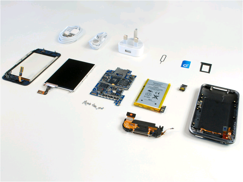
iPhone-3GS
Source: iFixit CC BY-NC-SA 3.0
Mobile phone components
| A18 SoC, 8GB LPDDR5 SDRAM, Kyoxia 128GB NAND Flash-Speicher |
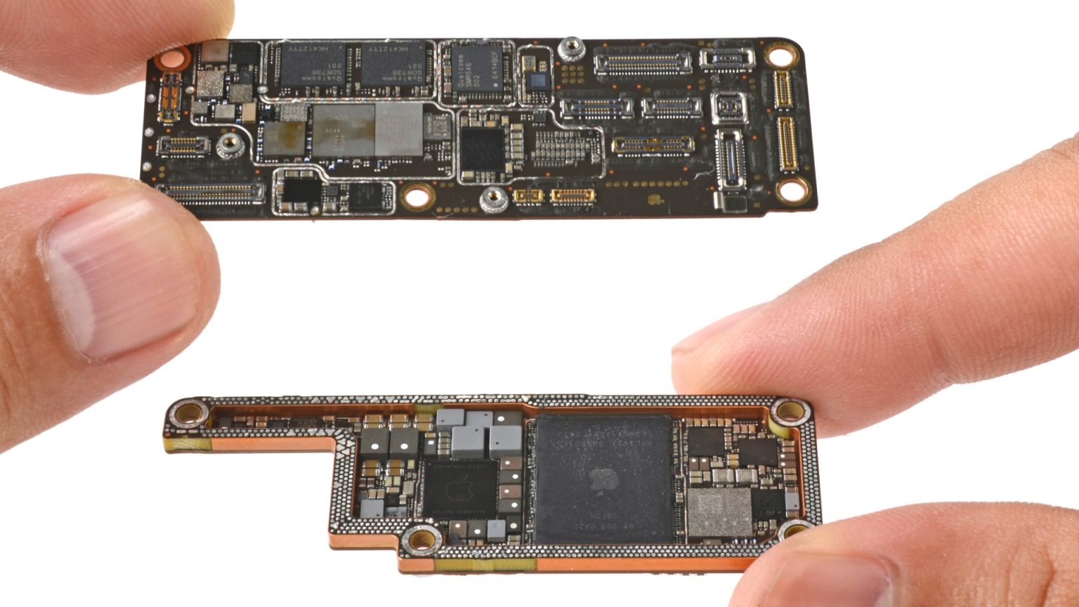 |
It is also very interesting to see the 3D integration since one PCB sits on top of the other.
Mobile phone main board
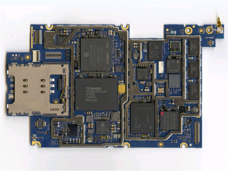 Source: iFixit CC BY-NC-SA 3.0 |
Samsung ARM processor S5PC100 600MHz 16 GB of Toshiba NAND flash memory NOR Pseudo SRAM Numonyx 256MB DDR SDRAM Analog Broadcom, Infineon Power Management Infineon, NXP |
MOSFET Transistor
  Quelle Vollrath
|
 Quelle Vollrath
|
| Technology | RN | RP | COX | Vthn | VDD | IDD | gmmax | gdmax | ft | Model |
| 1 μm | 15kΩL/W | 45kΩL/W | 1.75fF WL/F2 | 1V | 5V | 3 mA | cmosedu_models N_1um | |||
| 600 nm | ΩL/W | ΩL/W | fF WL/F2 | V | mA | C5_models | ||||
| 50 nm | 34kΩ/W | 68kΩ/W | 62.5aF WL/F2 | 0.3 V | 1 V | mA | cmosedu_models N_50nm |
MOSFET
A MOSFET (Metal oxide semiconductor field effect transistor) has the terminals gate (G), source(S), drain(D) and bulk(B). The gate controls current flowing between source and drain. There is a threshold voltage Vth which is needed to enable current flow. A bulk potential and bulk connection can change threshold voltage. Therefore bulk connections are needed to guarantee a stable threshold voltage.
There are enhancement mode PFETs and NFETS available making CMOS (complementary MOS) circuits possible. Enhancement mode FETS have a threshold voltage so that no current is flowing with 0V between source and gate.
NFETs have a positive threshold voltage, PFETS have a negative threshold voltage.
Transistor representation
Transistors as electrical components can be small black boxes with 3..4 wires. They are represented in a schematic as a symbol. In microelectronics a transistor is represented by a red rectangle (polysilicon) crossing a green rectangle (diffusion). Connections betweeen different colored areas are represented by black boxes between overlapping colored rectangles. Metal lines for connections are drawn as blue, violet or pink boxes.
In microelectronics circuits are built by transfering a transistor schematic to a layout (colored shapes). There are design rules limiting the size and distance of these colored boxes due to the limitations of the manufacturing process.
Minimum feature size and transistor area
The minimum total area of a transistor is based on the minimum feature size F.
The minimum feature size is the smallest pattern which can be realized in a given manufacturing process. The minimum feature size is depending on the wavelength of the used light source for the photoprocess used to transfer patterns with a mask onto the photoresist on a chip. A MOSFET uses at least 3 connections with minimum square area of F2. Since there should be no shorts a distance to the next feature should also has a minimum distance of 1 F. Therefore 3 connections and one active transistor area, where a red and green line are crossing, with isolation require:
4 * 4 F2 = 16 F2
Design Entry
|
Schematic Layout Graphical State machine VHDL SystemC C/C++ |
  |
  |
Result: Integrated Circuit
Courtesy of Intel
http://www.intel.com/pressroom/archive/releases/2008/20081117comp_sm.htm
http://download.intel.com/pressroom/kits/corei7/images/Nehalem_Die_Shot_3.jpg
2025 Serial CPU Investigation
|

|
Old Moore's Law (2011): Transistor count

Every 2 years the number of transistors per area doubles.
Each year manufacturing productivity gains are about 30%.